Hi All.
I currently use my computer for various DSP functions - EQ, XO, phase correction, volume control. The problem, although my soundcard measures amazingly (Asus Xonar D2), it has ground loop problems - in particular, I can't get it to shut up! I've tried a number of different things, and I've decided to try using transformers on the output.
I've already got six Edcor wsm 10k/10k line matching transformers. I'm currently working up an opamp output stage for each transformer, because I assume I can't just leave the secondaries of the transformers flapping in the breeze. Correct? I don't really want to, but I think I have to.
The schematic is mostly done, I'm doing the layout now. I'll post them when I can. A lot of trouble for a little ground hum...
Any feedback would be appreciated!
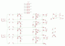
here is the schematic for 4 of the 6 channels of the soundcard isolator.
the transformers go between the pads on the left.
There is a rotary switch (4p3t) in the middle of the circuit, which allows 0, 10 and 20 dB of attenuation before the opamp. This is to allow the soundcard to be operating with less digital attenuation. The switch is in the middle/top of the schematic, but all the connections are not drawn.
The schematic is still a work in progress.
Attachments
Well, I ditched the opamps.
I now know why people don't use input transformers more - I can't get them to be quiet!! $#%$%$#$
I've been working on it for two days. I don't know what the issue is. The input transformer is more than two feet from the power transformer, I've tried all sorts of shielding and orientation, and it is as noisy as the computer that was the first problem.
If I place the transformer and shield in a very exact location (which I can't keep them at), the noise is 'only' -80dB - but in pretty much every other place, it is at best -60 to -70dB down. So frustrating!! The power amp itself has a noise floor of about -110dB, so I'm not very excited about the transformers right now...
Bifilar wound output trafos fed directly from the card outputs would be best, if the output impedance of the card is low enough (150 ohms or so).
Trafos built expressly for output duty CAN be left flapping in the breeze, input trafos cannot. They can be a PITA to get set up right. Also, output trafos are much less susceptible to interference, and some are available in mumetal cans for zero interference.
Trafos built expressly for output duty CAN be left flapping in the breeze, input trafos cannot. They can be a PITA to get set up right. Also, output trafos are much less susceptible to interference, and some are available in mumetal cans for zero interference.
After more looking, I came across this helpful thread. A lot of people have similar problems - ground loops and other noises from their PC's...
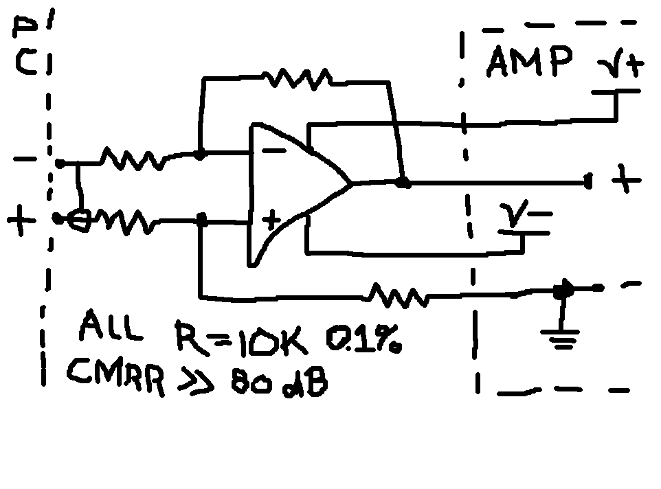
Anyway, in this thread, poobah posted this schematic:

I threw one together on a bread board, and it seems to work, so my thinking is to modify the input of my power amp (which also has a differential input, but I'm not using it that way).
My power amp is a 6-channel beast I've been unofficially calling "Quasimodo", just because it has become so ugly. But it works. Its based on the LME49830 opamp, and the power transformer is a 1300W monster I got for free from 'papa'.
Here is the input stage, as it is now:
I think all I need to do is unground the bottom the Ci1, but keep it attached to the shield of the RCA connector J4 (which will also be ungrounded). Then it should be operating in differential mode, no?
I'd like to lower the total gain of the amp, so I'm going to change Ri from 249ohms to somewhere around 850ohms. I suppose I also have to change Rin from 249 to 850ohms, to keep things balanced?
I'll post back when I get to it...
Anyway, in this thread, poobah posted this schematic:

I threw one together on a bread board, and it seems to work, so my thinking is to modify the input of my power amp (which also has a differential input, but I'm not using it that way).
My power amp is a 6-channel beast I've been unofficially calling "Quasimodo", just because it has become so ugly. But it works. Its based on the LME49830 opamp, and the power transformer is a 1300W monster I got for free from 'papa'.
Here is the input stage, as it is now:
An externally hosted image should be here but it was not working when we last tested it.
I think all I need to do is unground the bottom the Ci1, but keep it attached to the shield of the RCA connector J4 (which will also be ungrounded). Then it should be operating in differential mode, no?
I'd like to lower the total gain of the amp, so I'm going to change Ri from 249ohms to somewhere around 850ohms. I suppose I also have to change Rin from 249 to 850ohms, to keep things balanced?
I'll post back when I get to it...
Hi All.
I currently use my computer for various DSP functions - EQ, XO, phase correction, volume control. The problem, although my soundcard measures amazingly (Asus Xonar D2), it has ground loop problems - in particular, I can't get it to shut up! I've tried a number of different things, and I've decided to try using transformers on the output.
I've already got six Edcor wsm 10k/10k line matching transformers. I'm currently working up an opamp output stage for each transformer, because I assume I can't just leave the secondaries of the transformers flapping in the breeze. Correct? I don't really want to, but I think I have to.
The schematic is mostly done, I'm doing the layout now. I'll post them when I can. A lot of trouble for a little ground hum...
Any feedback would be appreciated!
Did you try using balanced input amplifiers? Yes I know your PC is unbalanced. Tie the '-' inputs to the sleeve of the 3.5 mm connector. The '+' inputs go to the tip and sleeve. Do NOT connect the 'grounds' together directly. You can try a 100 ohm resistor just to keep the grounds loosely coupled. Do this for each of the 3.5 mm connectors on the outputs. The 'signal' lines have signal plus ground noise while ground has just noise. The differential amps will subtract the noise from 'signal plus noise' and leave you with signal. I've done this many times and it also works with analog video hum. Remember that the accuracy of the noise cancellation depends heavily on the match of the resistors but you can buy chips like this with precision trimmed resistors in the package.
http://www.analog.com/static/imported-files/data_sheets/SSM2141.pdf
TI / Burr Brown has these also.
G²
Tie the '-' inputs to the sleeve of the 3.5 mm connector. The '+' inputs go to the tip and sleeve. Do NOT connect the 'grounds' together directly. You can try a 100 ohm resistor just to keep the grounds loosely coupled.
I think you have got it slightly wrong there, for a start you are shorting the signal to ground. Cold (-) input goes to sleeve, hot (+) input goes to tip, and ground to sleeve through 100 ohms.
Did you try using balanced input amplifiers?
that is just what I was talking about in my previous post. I haven't tried converting my amp yet, but I will. I'm not too sure about the changes I need to make though.
- Status
- This old topic is closed. If you want to reopen this topic, contact a moderator using the "Report Post" button.
- Home
- Source & Line
- Digital Source
- Transformers on the Output of a Soundcard
