Hi,
I have an unexplained fetish for Sherwood products. I know they are far from brilliance, but as i said it's a fetish.
I have had a broken CD player in the storage for a few years that I tried to fix several times and didn't have any success. About a month ago I decided to look for a full service manual for it. I found and bought one.
A few days later the player was playing and I was VERY happy with it.
All it took was to go through the proper alignment procedure, this was quite easy having the related documents.
In order to squeeze a little more out of it I replaced two main caps on the PS and changed the diodes to 1n5819 fast recovery diodes (this may have to do with the problem ?)
The CD worked like a charm for something like 4-5 days strait and I left it switched on and returned to my regular CD player.
About a week has passed and I found it today with no life signal:
1) When switching on only the LCD back-light lights up.
2) No keys action - on any key (door won't open, play will not play - nothing).
3) No laser action, at all.
4) On the power supply diodes seem to be in perfect working order.
5) I can measure +5VDC -5VDC out of the PS at the regulators and on various ICs on the PCB.
I have expected it to be PS related but the PS seems to be fine. I'm running out of ideas, could it be the CPU ? How do I go about checking the CPU ? What else can it be ?
As I said, I have a full service manual for this machine. I will gladly send it to anyone interested or willing to help.
Please help ...
Last edited:
Are there any digits or segments on the display showing ?
Is it a "real fault" or something that has happened to the player")
You need to be 100% sure all supplies are correct... 5 volts reaching all IC's
Faced with something like this my preferred method of fault finding would be to use a 'scope to check ALL pins on the main CPU using the 'scope to measure DC voltages as well. If that showed nothing then do the same on the other chips.
Experience says "it's never the IC" so unless something has hapened to the player... voltage spike etc from working in the PSU then the IC's would be the very last thing to suspect.
Make sure the clock and data lines have 5 volts pk pk of signal on them.
Is the keypad OK... a stuck key can inhibit things, so check the keyscan data lines and make sure no key is returning a signal when it shouldn't.
Is it a "real fault" or something that has happened to the player
You need to be 100% sure all supplies are correct... 5 volts reaching all IC's
Faced with something like this my preferred method of fault finding would be to use a 'scope to check ALL pins on the main CPU using the 'scope to measure DC voltages as well. If that showed nothing then do the same on the other chips.
Experience says "it's never the IC" so unless something has hapened to the player... voltage spike etc from working in the PSU then the IC's would be the very last thing to suspect.
Make sure the clock and data lines have 5 volts pk pk of signal on them.
Is the keypad OK... a stuck key can inhibit things, so check the keyscan data lines and make sure no key is returning a signal when it shouldn't.
1) Thanks ! I really need someone to help me with this one. I am quite lost, and I don't know how to tackle this one.
2) No, sadly no digits, at all, only backlight.
3) I have no idea what caused this, I'm not sure what you mean by 'real fault' , the cd was on for a couple of days, (not in use, but on), (about a week or so), and I wanted to use it and then I saw something was wrong with it. At first I thought one of the diodes on the PS might have blown (since I replaced these with fast recovery ones), but all 4 seem to be fine.
4) I started checking the IC's to see if all get 5V and I wanted to consult with someone to see I am not missing anything stupid...
5) I will check with a scope to see how signals at the cpu look like, although I'm not sure what I am looking for. (good call about the clock, I will check and see if its running smoothly...)
6) Keypad should be fine. definatly no stuck button. I will check it electronically
I will let you know what I find.
Again, thanks.
Since the entire player, but for the output stage chips, runs off of those single 7805 & 7905 regulators, it seems very likely that one or the other has either crapped out or fried it's solder connections, except that I now see that the display backlamp runs from +5 to -5 rails, so full brightness lamp means both regulators are putting out. However, you should definitely check for proper voltages from the two regs, and check ac voltage on the same lines as well. If you have more than 100mV AC on either supply line, you've got dying lytic caps before or after the regs, which could flake out the uproc. Stuck button is a good thought, as would be a failed uproc reset circuit, but the player went dead apparently while running, so it rules out both of these scenarios.
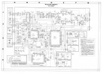
From the diagram, looks like a really, really cheaply made player. Doesn't mean it can't sound decent, though.
From the diagram, looks like a really, really cheaply made player. Doesn't mean it can't sound decent, though.
Hi stephensank,
I have checked 5VDC on various chips (those that aren't SMD, those were easier to check at the moment) so I think regs are running fine. I will check AC ripple on both DC supplies. I do hope it is one of the electrolytic caps, it could explain allot, since it's a very old player that was stored in a closet for a very long time.
I agree about the player being a very simple/cheaply made one. I have to say that for the 4 days it was playing, (and after I replaced diodes and the two main caps in the PS), it exceeded my expectations from it. It actually does sound quite nice.
In any case I have some thorough checking to do, (as you and mooly suggested), I am hoping I'll get to do everything later on today. I'll be sure to update.
Thank you !
I really appreciate the help, and as I said, I DO need it, I'm not sure how to tackle this one on my own.
OK, here are my findings, I hope this advances anything:
1) DC looks fine, nothing near 100mV ripple (@5vdc + or -), at worse case I get less than 10mV. I really think the PS is fine.
2) All ICs get the +5vdc supply (except the 4558@24Vdc and 4560@12vdc Op-amps).
3) 7805 Reg. seems to be heating up more than 7905, which seems to make sense because:
4) I think something is shorting the hell out of the PS. On the u processor most lines give me solid +5vdc , all push buttons give me solid +5vdc on all contacts, all outputs to the LCD display give me solid +5vdc.
5) I cannot say I picked up any digital signals I recognized with the 'scope, but I did see some digital communication activity. A few lines beween digital signal processor (cxd1167q) and the servo signal processor are passing data, and I also find some communication between the two ICs mentioned, the digital filter (sm5807) and the A/D (upd6372).
At the CPU, the only thing that may look like a signal is a single pulse on pin 64 designated SCQR which I do not know what it stands for. Pulse is: 166uSec wide and about 5V tall.
All other pins are DC at various levels, most pins are at +5vdc.
6) I got the clock. its even still calibrated funny thing is, it looks like there are two clocks. the one that the service manual refers to (in the adjustment proc.) is the PLL at the servo signal processor (cxa1082a). this one looks fine.
But there is another crystal oscillator, connected to the sm5807 digital filter, which does not oscillate AT ALL. this cannot be good.
This is about it. if anyone has an idea, I would love to hear it.
1) DC looks fine, nothing near 100mV ripple (@5vdc + or -), at worse case I get less than 10mV. I really think the PS is fine.
2) All ICs get the +5vdc supply (except the 4558@24Vdc and 4560@12vdc Op-amps).
3) 7805 Reg. seems to be heating up more than 7905, which seems to make sense because:
4) I think something is shorting the hell out of the PS. On the u processor most lines give me solid +5vdc , all push buttons give me solid +5vdc on all contacts, all outputs to the LCD display give me solid +5vdc.
5) I cannot say I picked up any digital signals I recognized with the 'scope, but I did see some digital communication activity. A few lines beween digital signal processor (cxd1167q) and the servo signal processor are passing data, and I also find some communication between the two ICs mentioned, the digital filter (sm5807) and the A/D (upd6372).
At the CPU, the only thing that may look like a signal is a single pulse on pin 64 designated SCQR which I do not know what it stands for. Pulse is: 166uSec wide and about 5V tall.
All other pins are DC at various levels, most pins are at +5vdc.
6) I got the clock. its even still calibrated
funny thing is, it looks like there are two clocks. the one that the service manual refers to (in the adjustment proc.) is the PLL at the servo signal processor (cxa1082a). this one looks fine. But there is another crystal oscillator, connected to the sm5807 digital filter, which does not oscillate AT ALL. this cannot be good.
This is about it. if anyone has an idea, I would love to hear it.
I think the missing clock is the problem... when you power up is there any clock signal on pin 4 of the digital filter which looks like it's the main "clock out" for the whole unit. The oscillator around the crystal may be at low amplitude... it's what comes out of pin that's important. Should be 5 volts pk/pk.
OK, this keeps getting stranger...
Did what you asked.
I get different results every time i switch the CD on.
Most of the times when I switch the CD on, I get only DC (about 80mV) on pin 4 (picture 1). in this "state" I get nothing on pin 2. not even dc - (the oscillator itself).
But sometimes I switch the CD on and get what you see in picture 2, steady. which is strange.
When I get into this "state" pin 2 flickers a signal like in picture 3 every half a second or so.
In any case pin 4 does not look like it should.
I don't understand how come I get a clock signal at the PLL ?
What should I do ?
Attachments
Last edited:
I would look round that IC really carefully... although it's looking like it may be faulty.
Know it sounds silly but check every pin with the scope, if only to make sure that two adjacent pin aren't shorted with a solder blob somewhere on the PCB. Check the ground pin with the scope too, just to be sure. 5 volts OK on the chip ? If all that proves nothing then it does look like the IC is faulty. No dry joints on the crystal ?
Know it sounds silly but check every pin with the scope, if only to make sure that two adjacent pin aren't shorted with a solder blob somewhere on the PCB. Check the ground pin with the scope too, just to be sure. 5 volts OK on the chip ? If all that proves nothing then it does look like the IC is faulty. No dry joints on the crystal ?
Mooly, thanks.
No solder blobs at any pin.
I've re soldered the crystal and made sure contacts are fine.
I checked earlier every pin with the scope. as I wrote there seems to be some active data lines between this IC and the D/A. nothing I can define as "out of the ordinary" - except of course - NO CLOCK .
I checked the ICs grounding resistance to the PCB ground -zero. looks OK.
Would you suspect the two 18pF caps driving the crystal ?
Where would you suggest I can look for SM5807 ?
No solder blobs at any pin.
I've re soldered the crystal and made sure contacts are fine.
I checked earlier every pin with the scope. as I wrote there seems to be some active data lines between this IC and the D/A. nothing I can define as "out of the ordinary" - except of course - NO CLOCK
.I checked the ICs grounding resistance to the PCB ground -zero. looks OK.
Would you suspect the two 18pF caps driving the crystal ?
Where would you suggest I can look for SM5807 ?
Well, no.
I have checked both the PS and the cpu very thoroughly today, and also had allot of help I have described everything I found in my previous posts.
No clock signal at the cpu.
Got a PLL signal but as it appears, no master clock.
Looking more into it later on...
thanks.
I have checked both the PS and the cpu very thoroughly today, and also had allot of help
I have described everything I found in my previous posts.No clock signal at the cpu.
Got a PLL signal but as it appears, no master clock.
Looking more into it later on...
thanks.
OK,
Here are the latest checks and the results:
I have downloaded the data sheet for the digital filter IC and I understood that there are 4 outputs, in use, out if this IC (sm5807). pins 4,12,14,15.
I disconnected the 680 resistors leading out of pins 12,14,15 (R166,R165,R164 respectively) switched on, and nothing much happened.
BUT :
After disconnecting pin 4 (R162) when I switch on and wait for about 10 second, the display appears, very segmented, and slow (only some of the display at any given moment - Multiplexed ?), and if I press a button long enough, I get some action. For example the door open/close button reacts normally after holding it long enough. Plus, I get pickup activity. the pickup moves. (I think it is searching for a CD).
At first I didn't understand why everything seems to be slow, but then I hung the 'scope on the resistor's disconnected pin and I saw some (inductive?) 40-50KHz oscillations on it. about 300 times slower than the crystal's freq.
I changed the two caps (18pF) to new 15pF ones just to make sure it's not the caps. and even changed the crystal to another 16.9344Mhz crystal.
No improvement.
I then tried to "inject" a clock signal of my own. I decided to carefully connect my bench oscillator to the resistor's pin and "push" a clock into the circuit (relative to the PCB's ground).
Well this didn't work. I'm not sure why.
Maybe because my bench oscillator only gets to about 10MHz. I didn't have the guts to drive the signal above 4V PK-PK, so this could be another reason.
If anyone can think of anything more I can check aside from replacing the sm5807 I will be happy to do so.
I already ordered the IC from Ebay. It might take a while 'till it gets here.
I am wondering,
In case it is the IC, did it go because I did something bad ? Maybe the fast recovery diodes in the PS ? What could have caused this ?
Thanks guys,
Sephy.
I think you have done all you can, and it looks like the IC at the moment. The fact things happened when you disconnect pin 4 is promising too.
When you use a generator (depending on what it's like of course) 4 volts pk/pk output will be -/+4volt centered around ground... in other words your swinging the clock line above and below ground by 2 volts.
If the generator hasn't a DC offset you can set, what you need to do is AC couple the generator output with a 0.1uf or so together with a 1n4148 at the output end of the cap to clamp the signal to ground. Anode to ground.
Why/if ? the IC failed... dunno... if the PSU is OK then it's OK. High speed diodes wouldn't cause a problem. Worth checking no drys on the regs that could spike the rails.
Seems like the IC is used in Denon,
Dcd800 Sm5807Cp I/C Denon
Got the IC ...
Well, seems like you were right again, I'll say it with you, "ITS NEVER THE BIG IC!" .
I got the IC (sm5807 digital filter...), and replaced it. as you might have guessed by now, the player is playing again !
I still want to know how the old IC died. I really hope this won't happen again...
I am ecstatic.
thanks for everything !
Liquias.
Well, seems like you were right again, I'll say it with you, "ITS NEVER THE BIG IC!"
.I got the IC (sm5807 digital filter...), and replaced it. as you might have guessed by now, the player is playing again !
I still want to know how the old IC died. I really hope this won't happen again...
I am ecstatic.
thanks for everything !
Liquias.
- Status
- This old topic is closed. If you want to reopen this topic, contact a moderator using the "Report Post" button.
- Home
- Source & Line
- Digital Source
- Help needed. Sherwood CD1000C