What are the measurements that I can take to ensure this.
I am an EE, and have taken a class on transmission lines and fully understand the reflecting waves, and overall wave propogation. If my education serves me, I should be able to take my 75 ohm digital cable and connect it to the source and receiver and measure it with an ohm meter and see 38.5 ohms. This should be true in either direction, correct?
Well, I took a measurement yesterday and into my DAC (scott nixon) it measured 38.5 exactly after I subtraced my series resistance. Measuring into my H/K FL8550 I see around 400 ohms of resistance. Now, this seems a little odd, maybe it is because it was switched off, I dont know.
What other tests can I do to make sure I am getting the cleanest signal transfer. All I really have to measure with is a DMM.
Also, what can I do to aleviate this problem if it is indeed true.
Thanks for the help guys,
Paul Hilgeman
Eye pattern with a DMM?
I know you said that you only have access to a multimeter, but if you can borrow a scope, looking at the eye pattern will tell you the most.
Just a hunch, but the 38.5 ohm impendence sounds a little like a double termination.
(Attached photo is not of PSDIF so don’t get freaked out about period and amplitude of waveform)
Attachments
If you remember your transmission line theory, you will also remember that transmission line effects only become significant when the cable length is a reasonable proportion of signal wavelength. Or, to put it another way, a DMM (using 0Hz) is virtually useless.
Clean eye patterns are the common thing to look for, as mentioned by Da5id4Vz, but you need a seriously fast oscilloscope.
A possibility that doesn't need quite such a good oscilloscope is to look at the cleanliness of the signal as it enters the transmission line compared to the way it leaves. If the two are not the same (on a short <2m cable), the line must be misterminated. You can work out which by terminating the line at your oscilloscope with a 75R through termination (or, not quite as good, a T-piece and 75R term) and seeing if that changes the waveform. If it does, it suggests that your original terminating equipment is not 75R.
To be honest, it's a lot easier simply to build a little video op-amp circuit to drive the cable from 75R, and a video op-amp buffer at the far end. That way, you know your cable is terminated properly (always assuming that the cable genuinely is a 75R transmission line).
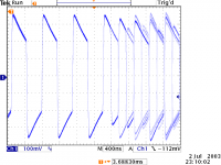
You provoked my interest, so I looked at the output of a Marantz CD63mkIIKI (GTI, turbo etc) terminated in 75R. It's a disgrace. We ought to see a waveshape similar to that given by Da5id4Vz. The first part of the waveform is the run-in code, the second (changing) is the music data. The downward slope is due to low frequency loss:
Attachments
Well, the only scopes that I can get are about 20 MHz, I am not sure if that is fast enough.
I am not sure if I learned different terminology, but I dont know what the eye-pattern is.
I like the idea of the additional opamp filter at the output.
I know that my input is fine, as I have already verified that it shows a 38.5 ohm impedence at the other end of the line.
I also trust the input, it is a Scott-Nixon DAC. Check www.scott-nixon.com
Thanks for all of the help. I may not be able to reply until monday, so I apologize in advance.
-Paul Hilgeman
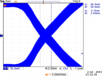
20MHz is slow. I used a 300MHz oscilloscope (and would have liked a faster one) to produce the eye pattern (second trace). The eye is the bit in the middle of the "X". It ought to have zero width.
The video op-amps I suggested are not intended as filters, but as buffers that allow correct termination.
38.5R resistance at the far end of the line does not necessarily mean anything. If it is transformer input, it could be 1R DC, but 75R at SPDIF. I looked at the URL and noted that there didn't appear to be any input buffer chip. I wouldn't be in the least surprised to find that the DAC doesn't terminate the cable properly. However, the source is far more important, and as my example shows, it's often wrong.
An article that might be worth reading:
I haven’t read much of this article, so I cant vouch for its quality, but a quick skim shows it to have a lot of information about CD's SPDIF and eye pattern interpretation.
http://members.chello.nl/~m.heijligers/DAChtml/digcom/digcom.html
I found it by googling "spdif eye pattern".
EC8010, I didn’t think the pattern you posted looked to bad. Your Tek seems to display its quanitised results differently from the HP output I posted. Zooming out a notch in both sweep time and amplitude I think would give a better image of an entire symbol and not just a single crossing. The fatness of the lines I think would be an indication of the jitter you mentioned. Ive used a 100 MHz scope to look at eye patterns, but as I recall it involved dimming the lights to observe the trace.
Da5id4Vz,
the eye pattern trace was obtained by triggering (with holdoff) at word rate, then using "B" timebase to expand, and setting persistence to infinite, resulting in the fat lines, which, as you observe, indicates the jitter.
And yes, Teks display differently to HPs. There are times when I would prefer an HP, but it took enough dithering before I bought the Tek.
No, I dont believe the input to the DAC is buffered in any way, it comes in through the RCA jack, and then goes to a 75 ohm resistor from the center to outside pin. After which it goes along about .5cm of PCB trace to the CS8412.
I am guessing that it is probably OK, but it is the output that I need to worry about. Are there any write-ups, or would anyone here like to help me add in a video buffer to my CDP output?
Thanks,
Paul Hilgeman
I am guessing that it is probably OK, but it is the output that I need to worry about. Are there any write-ups, or would anyone here like to help me add in a video buffer to my CDP output?
Thanks,
Paul Hilgeman
- Status
- This old topic is closed. If you want to reopen this topic, contact a moderator using the "Report Post" button.
- Home
- Source & Line
- Digital Source
- Want to check and verify that I am getting best possible digital signal transfer???