Hello
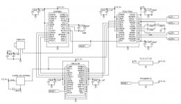
I would like to connect a TDA1541A to a SRC4192 and a DIR9001
I've done a schematic of it.
I did not include the I/V amp in the schematic but there would be a low pass filter in the I/V amp.
Is my schematic would work ok or do it have any errors ?
Any suggestions ?
Thank you
Bye
Gaetan
I would like to connect a TDA1541A to a SRC4192 and a DIR9001
I've done a schematic of it.
I did not include the I/V amp in the schematic but there would be a low pass filter in the I/V amp.
Is my schematic would work ok or do it have any errors ?
Any suggestions ?
Thank you
Bye
Gaetan
Attachments
Last edited:
Hello
I was not sure if I did chose the right output mode for the SRC4192 to go in the TDA1541A .
For power amps I use LTspice, but for digital things, since I have some concentrations problems on small details and drawing, I alway ask guys to check my schematics, in case of errors.
Thank you
Bye
Gaetan
I was not sure if I did chose the right output mode for the SRC4192 to go in the TDA1541A .
For power amps I use LTspice, but for digital things, since I have some concentrations problems on small details and drawing, I alway ask guys to check my schematics, in case of errors.
Thank you
Bye
Gaetan
I'm not sure if practice deviates from theory with this chip. But you have your reset pin connected directly to +3.3V. You may need to check this.
The datasheet says:
"The SRC4192 and SRC4193 may be reset using the RST
input (pin 13). There is no internal power on reset, so the
user should force a reset sequence after power up in order
to initialize the device. In order to force a reset, the reference
clock input must be active, with an external clock source
supplying a valid reference clock signal (refer to Figure 2).
The user must assert RST low for a minimum of 500
nanoseconds and then bring RST high again to force a reset."
Hi,
Given that you need a PCB for all these SMD chip's anyay, why not just put a bunch of jumpers (or pairs of config resistors to ground/+Vdd) for all mode and other config pins on all chip's where they make any sense at all. This way you can easily correct any mistakes.
I always do this on my prototype PCB's.
Ciao T
I was not sure if I did chose the right output mode for the SRC4192 to go in the TDA1541A .
Given that you need a PCB for all these SMD chip's anyay, why not just put a bunch of jumpers (or pairs of config resistors to ground/+Vdd) for all mode and other config pins on all chip's where they make any sense at all. This way you can easily correct any mistakes.
I always do this on my prototype PCB's.
Ciao T
Hi,
Given that you need a PCB for all these SMD chip's anyay, why not just put a bunch of jumpers (or pairs of config resistors to ground/+Vdd) for all mode and other config pins on all chip's where they make any sense at all. This way you can easily correct any mistakes.
I always do this on my prototype PCB's.
Ciao T
Hello Thorsten
Hopefully there is only the SRC4192 and a DIR9001 who are SMD. I really don't like SMD parts.
The SRC4192 seem, for me, the only way to use the TDA1541A at 96khz without oversampling, there was a thread about that in the digital-source forum section some time ago.
Thank
Bye
Gaetan
Last edited:
Hi,
If you do not use 0603 SMD capacitors around these chips you will not get anywhere the performance they are capable of.
The SRC4192 performs asynchronous sample rate conversion.
In principle this is very much the same fundamental process as oversampling, the main difference being that oversampling generally uses integer based math (whole numbers) and is simpler, while up-sampling uses non-integer math (fractions, floating point) and hence is more prone to errors.
So to say that the circuit you show allows the TDA1541 to be used without oversampling at 96KHz is literally true, as in "upsamplig is NOT oversampling", but it is severely misleading if what you want is to operate at 96KHz without digtal filter.
I use my TDA1541 DAC routinely at 96KHz (I have many recordings at that sample rate on my Media PC's harddrive) without a SRC4190 in there, just a CS8414 with a discrete frontend based on Pat "Jocko Homo" DiGiaccomo's SPDIF circuitry directly into the TDA1541 (CS8414 set to output 16 Bit I2S).
I will eventually update the fronend to a WM8805, which is the only receiver worth bothering with in this day and age and can also provide the TDA1541 with 176.4 & 192KHz 16 Bit I2S.
Ciao T
Hopefully there is only the SRC4192 and a DIR9001 who are SMD. I really don't like SMD parts.
If you do not use 0603 SMD capacitors around these chips you will not get anywhere the performance they are capable of.
The SRC4192 seem, for me, the only way to use the TDA1541A at 96khz without oversampling,
The SRC4192 performs asynchronous sample rate conversion.
In principle this is very much the same fundamental process as oversampling, the main difference being that oversampling generally uses integer based math (whole numbers) and is simpler, while up-sampling uses non-integer math (fractions, floating point) and hence is more prone to errors.
So to say that the circuit you show allows the TDA1541 to be used without oversampling at 96KHz is literally true, as in "upsamplig is NOT oversampling", but it is severely misleading if what you want is to operate at 96KHz without digtal filter.
I use my TDA1541 DAC routinely at 96KHz (I have many recordings at that sample rate on my Media PC's harddrive) without a SRC4190 in there, just a CS8414 with a discrete frontend based on Pat "Jocko Homo" DiGiaccomo's SPDIF circuitry directly into the TDA1541 (CS8414 set to output 16 Bit I2S).
I will eventually update the fronend to a WM8805, which is the only receiver worth bothering with in this day and age and can also provide the TDA1541 with 176.4 & 192KHz 16 Bit I2S.
Ciao T
Hello Thorsten
My schematic are just a TDA1541A version of the Micro Dac schematic, that one use a PCM1794A dac chip, but I was presuming that the TDA1541A would sound much better than the PCM1794A. So I've adapted the Micro Dac schematic for a TDA1541A chip.
Here is the original schematic using a PCM1794A dac chip.
Btw, I've seen that the reset of the DIR and SRC chip need a delay of arround 200ms, it need to use a TPS3809K33.
Thank
Bye
Gaetan
Attachments
Last edited:
Hi,
I use my TDA1541 DAC routinely at 96KHz (I have many recordings at that sample rate on my Media PC's harddrive) without a SRC4190 in there, just a CS8414 with a discrete frontend based on Pat "Jocko Homo" DiGiaccomo's SPDIF circuitry directly into the TDA1541 (CS8414 set to output 16 Bit I2S).
I will eventually update the fronend to a WM8805, which is the only receiver worth bothering with in this day and age and can also provide the TDA1541 with 176.4 & 192KHz 16 Bit I2S.
Ciao T
Hello Thorsten
Using the CS8414 at 88khz or 96khz, to have a higher sampling frequency for the TDA1541A, would not work for a 44.1khz SPDIF input signal ?
Thank
Bye
Gaetan
The SRC4192 seem, for me, the only way to use the TDA1541A at 96khz without oversampling
Gaetan
You can achieve this if you find a stand alone media player or NMT that will output high resolution audio, and then tap the i2s lines from one of these units.
Then you can play 96khz to the TDA1541 as a native format rather than upsampling.
Hi,
Of course it will play back 44.1KHz just fine, als 32KHz ^& 48KHz.
What it will not do is to up- or over-sample from 44.1KHz to a higher data rate.
Generally I would not recommend to attempt this anyway, as it cannot improve the the digitally encoded signal in any way.
Try instead to implement a low jitter connection or receiver and omit digital filters.
You would need to make sure to set the output from the SRC4192 to the correct format required by the TDA1541. That would be 16-Bit IS2 with BCK = 32*Fs.
There are many ways to handle the reset requirements. It is best to really read the datasheets and all the qualifications about reset conditions (e.g. which clocks need to be present etc.).
Ciao T
Using the CS8414 at 88khz or 96khz, to have a higher sampling frequency for the TDA1541A, would not work for a 44.1khz SPDIF input signal ?
Of course it will play back 44.1KHz just fine, als 32KHz ^& 48KHz.
What it will not do is to up- or over-sample from 44.1KHz to a higher data rate.
Generally I would not recommend to attempt this anyway, as it cannot improve the the digitally encoded signal in any way.
Try instead to implement a low jitter connection or receiver and omit digital filters.
My schematic are just a TDA1541A version of the Micro Dac schematic, that one use a PCM1794A dac chip, but I was presuming that the TDA1541A would sound much better than the PCM1794A. So I've adapted the Micro Dac schematic for a TDA1541A chip.
You would need to make sure to set the output from the SRC4192 to the correct format required by the TDA1541. That would be 16-Bit IS2 with BCK = 32*Fs.
Btw, I've seen that the reset of the DIR and SRC chip need a delay of arround 200ms, it need to use a TPS3809K33.
There are many ways to handle the reset requirements. It is best to really read the datasheets and all the qualifications about reset conditions (e.g. which clocks need to be present etc.).
Ciao T
Hi,
The differences are quite large.
If your tastes run in the same lines as mine, you probably do find the TDA1541 More to your liking.
In this case however, you will find it even more to your liking if you leave out the ASRC.
Ciao T
Do I was correct wen I presumed that the TDA1541A would sound much better than the PCM1794A, or the sonic differences are not so big ?
The differences are quite large.
If your tastes run in the same lines as mine, you probably do find the TDA1541 More to your liking.
In this case however, you will find it even more to your liking if you leave out the ASRC.
Ciao T
Hi,
The differences are quite large.
If your tastes run in the same lines as mine, you probably do find the TDA1541 More to your liking.
In this case however, you will find it even more to your liking if you leave out the ASRC.
Ciao T
Hello Thorsten
Since I like tube amp sound and I have a SS amp designed for musicality and not for numbers, I presume that my tastes are same than yours.
I will use the bypass switch on the SRC4192 , so it may be use it for some types of music recording only, or not using it at all.
Thank you for your help
Bye
Gaetan
Last edited:
- Status
- This old topic is closed. If you want to reopen this topic, contact a moderator using the "Report Post" button.
- Home
- Source & Line
- Digital Source
- About connecting a TDA1541A to a SRC4192 and a DIR9001