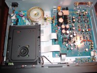
Here is a mod that solved quite a bit of distortion coming from the analogue side of my Marantz SA8001. The gain amplifier on this machine is quite hot leading to a really nice output, but in many newer CDs, this sends the equalizing amp over the top and it results in distortion inside the unit and in my older amps due to the too much output during loud passages, especially voices.
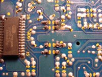
The mod involves replacing the 4 1.2K ohm resistors (R651 R652 R601 R602) that interface the DAC and the equalizing amp. Ideally, you can probably use 2.2K, 4.7K or 6.8K ohm which is what I used.
All distortion due to too much gain is now gone and it will not over drive my amps inputs as the signal is attenuated by about 25% or so.
Proceed at your own risk, I would not touch one of these units unless you have the skill and a problem already.
Attachments
You basically reduced the input signal. Because the noise of the HDAM stage will remain the same, you decreased the Signal/Noise ratio. It might be still OK, but it is a shame in my view.
I would rather lower the negative feedback resistor to decrease the gain or add a divider somewhere close to the output.
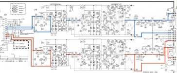
I don't have your schematic, but some similar one - red mark the places where I would make the above changes. It is also easier since you keep balanced stage... balanced (you have to match only 2 resistors, not four).
I would rather lower the negative feedback resistor to decrease the gain or add a divider somewhere close to the output.
I don't have your schematic, but some similar one - red mark the places where I would make the above changes. It is also easier since you keep balanced stage... balanced (you have to match only 2 resistors, not four).
Attachments
Last edited:
You basically reduced the input signal. Because the noise of the HDAM stage will remain the same, you decreased the Signal/Noise ratio. It might be still OK, but it is a shame in my view.
I would rather lower the negative feedback resistor to decrease the gain or add a divider somewhere close to the output.
I don't have your schematic, but some similar one - red mark the places where I would make the above changes. It is also easier since you keep balanced stage... balanced (you have to match only 2 resistors, not four).
Your idea about the feedback sounds good, the output from the DAC was way overcoming one of the amp stages downstream, rather than to try to single it out, I just went for the "top kill" and it worked. I could have probably used lesser resitors, but had 4 matched metal films in the drawer.
The sound before was unbearable on about 75% of my CDs. A remarkable improvement now, but as you state, I did sacrifice STNR level. The good thing is that new CDs are maxed out in signal and do distort in some instances on my other players, but not on this one after the mod.
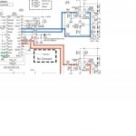
I have attached a schematic, would love to see what you recommend for the negative feedback resistor replacements, I may try it down the road. You'll see the DAC on the left side and RCA outputs for the 8001 on the dog legs all the way to the right. Signal paths are highlighted.
Only question I have about your suggestion is if the distortion occurs early in the differential amp stage, does changing the HDAM feedback resistor have any effect there? Thanks.
Attachments
Last edited:
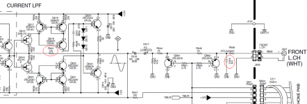
I would try first to attenuate the signal at the end - a resistor in place where C618,668 empty pads are (NC means not connected). Attenuation there is in a place with the highest level of signal so won't be that bad for SNR.
Other place would be feedback resistors R641, 691. I doubt that the whole thing is distorting due to high levels, rather your amplifier is to sensitive. That's why I won't change nothing drastically like the feedback or the differential stage.
If you change the R615,655 in the diff HDAM, then the filter freq change too, so that is a more involved change.
Last edited:
I would try first to attenuate the signal at the end - a resistor in place where C618,668 empty pads are (NC means not connected). Attenuation there is in a place with the highest level of signal so won't be that bad for SNR.
That was my first thought until I heard the distortion in the headphone tap that goes right before this point.
Other place would be feedback resistors R641, 691. I doubt that the whole thing is distorting due to high levels, rather your amplifier is to sensitive. That's why I won't change nothing drastically like the feedback or the differential stage.
If you change the R615,655 in the diff HDAM, then the filter freq change too, so that is a more involved change.
I agree with you on making the least involved change. The distortion was for sure inside the unit as I attenuated the end signal right at the RCA outputs to eliminate the amp, and no change. That left the other end as least involved and it works beautifully now. Come to think about it, the STNR was quite low before this mod.
What is a puzzle is why this mod was needed to make the unit listenable.
Seems very odd. CD has absolute limits on max output levels and it seems inconceivable that this is a design error. I would look for other causes, even something as simple as a supply issue to the analogue stages (low rails). A scope check would quickly reveal the problem using a test CD at 0db level. No music signal can ever exeed that level.
It could also be an issue with the muting circuit just quickly looking at the circuit. Easy to remove the four mute transistors to check.
Whatever the issue is... I think you are just fixing the symptoms and not the underlying cause.
It could also be an issue with the muting circuit just quickly looking at the circuit. Easy to remove the four mute transistors to check.
Whatever the issue is... I think you are just fixing the symptoms and not the underlying cause.
Hm,
I've been reading this thread and just wondering............................
The Marantz 8001 has the exact same analogue stage, after the dac, as the 7001, 8260 and 8400 players, right down to the spelling of AUDIO SUPLLY on the board. There are quite a number of these players floating about. Never heard of an issue as described here. Usually the issue with these is a transport/laser issue. It all sounds to me like something downstream from the player.
Replacing the resistor on the dac output and reducing the voltage output from 2.78V to about 1.5V doesn't seem a good idea as the filter circuit is based on the incoming 2.78V. Changing feedback resistor seems okay but maybe not do too much.
If you want better sound, always good to bypass the muting transistor circuit by just removing the wire link and running wire, or 75R resistor, from output cap to rca. You get a "click" sound when disc is ready to play, but the sound is easily heard to be better.
For the best sound out of these players, best to replace the whole analog stage after the dac. But that's not really the issue in the OP.
Looking at the OS schematic, there is NO WAY that circuit should be able to clip at 2.8V RMS. It should be able to swing damn near 7VRMS or so without clipping. I
So, I quite firmly believe that the problem is actually the muting transistors. I know for a fact that 2SC2240, an otherwise nice transistor, does not like being connected as an 'upside down' muting transistor, with grounded collector like this. When thus configured, they will ALWAYS eventually starting leaking current to ground.
I very strongly suggest that you either disconnect them, or replace them with 2SK117 or 2SK170 jfet, provided the mute line goes negative when unmuted, which it darn well should. I do this on all Nakamichi Dragons I rebuild & they work brilliantly; totally silent operation with no current leakage at all, and no discernible effect on sound. This is to replace the 2SC2878's, which do hold up reasonably well in that funky grounded collector muting config, where I used to install 2SC2240's in grounded emitter config, but the jfet's work better & never go bad.
Other than the stupidly chosen muting xstor config, looks like a nice output stage to me, if rather conventional.
BTW, do you have any experience with the KTC2875B (lesser version of 2SC2878A/B?)for the muting transistors?
I think you are wrong is some aspect - the usual configuration of muting transistors seems to be "backwards", because of the normal negative base voltage bias - which in fact polarize them "normally", with the collector being more "positive" compared with the base.
The only non-conventional voltage is the emitter one, that fluctuates around zero, with no base-emitter current.
On the other hand, I never saw JFET's in that position - I would assume the are worse (Schottky noise?)
Last edited:
I have found it ill advised to use any transistor with a KTC prefix, honestly. I avoid them. But, no, have never even seen a 2875.
As to the grounded collector configuration, I do very strongly consider that 'upside down' for an NPN transistor with a positive 'mute on' voltage, as these are generally done, and can say it is an absolute FACT that 2SC2240's only hold up well as muting devices when they are grounded emitter configuration.
And it is also quite common for JFET's to be used in the same capacity, and I have NEVER seen any muting jfet of any type go bad or cause any noise at all. I consider them ideal for the purpose.
Looking at the OS schematic, there is NO WAY that circuit should be able to clip at 2.8V RMS. It should be able to swing damn near 7VRMS or so without clipping. I
So, I quite firmly believe that the problem is actually the muting transistors. I know for a fact that 2SC2240, an otherwise nice transistor, does not like being connected as an 'upside down' muting transistor, with grounded collector like this. When thus configured, they will ALWAYS eventually starting leaking current to ground.
I very strongly suggest that you either disconnect them, or replace them with 2SK117 or 2SK170 jfet, provided the mute line goes negative when unmuted, which it darn well should. I do this on all Nakamichi Dragons I rebuild & they work brilliantly; totally silent operation with no current leakage at all, and no discernible effect on sound. This is to replace the 2SC2878's, which do hold up reasonably well in that funky grounded collector muting config, where I used to install 2SC2240's in grounded emitter config, but the jfet's work better & never go bad.
Other than the stupidly chosen muting xstor config, looks like a nice output stage to me, if rather conventional.
Sorry folks been away building speakers and just got back to this. Your potential diagnosis is right along with what I thought the errant behavior of the unit would point to. The headphone tap is before this muting circuit, it contained "less" distortion but still distorted noticeably on hot CDs. This left the problem upstream and a very easy fix was replacement of the coupling resistors from the DAC. I have 4 other Marantz players, and now this one is the only one I can count on to totally not distort with new hot CDs. To my ears at least, there has been no sacrifice to quality. The lesser output also allows me to use it with vintage pre/amps without distortion peaks.
Not sure how it got this way, but I think your suspicion makes sense. It still pops when you stop or eject the unit. Not sure about that, but not worth messing.
Thanks.
The headphone thing actually confirms my diagnosis of bad muting transistors. The headphone line is broken out from the output of the final stage, isolated from the muting xstors by just a 75ohm resistor. So, while there would be less distortion to the phones, there definitely would be some. Also, the popping clearly is being caused by dc leakage from the bad transistors. This combo of symptoms is very precisely what happens when you use 2SC2240's as muting devices in grounded emitter config., in my experience.
If you don't pull those xstors out, they will progressively start distorting the signal at lower levels, and leak more dc voltage. If you do replace them with 2sk117 or 2sk170 jfets, you simply have to 're-pin' them. These jfets, looking at the labeled side, are DGS(drain, gate, source, equivalent to collector, base, emitter), whereas the 2SC2240 is ECB, so arrange the leads accordingly.
If you don't pull those xstors out, they will progressively start distorting the signal at lower levels, and leak more dc voltage. If you do replace them with 2sk117 or 2sk170 jfets, you simply have to 're-pin' them. These jfets, looking at the labeled side, are DGS(drain, gate, source, equivalent to collector, base, emitter), whereas the 2SC2240 is ECB, so arrange the leads accordingly.
The headphone thing actually confirms my diagnosis of bad muting transistors. The headphone line is broken out from the output of the final stage, isolated from the muting xstors by just a 75ohm resistor. So, while there would be less distortion to the phones, there definitely would be some. Also, the popping clearly is being caused by dc leakage from the bad transistors. This combo of symptoms is very precisely what happens when you use 2SC2240's as muting devices in grounded emitter config., in my experience.
If you don't pull those xstors out, they will progressively start distorting the signal at lower levels, and leak more dc voltage. If you do replace them with 2sk117 or 2sk170 jfets, you simply have to 're-pin' them. These jfets, looking at the labeled side, are DGS(drain, gate, source, equivalent to collector, base, emitter), whereas the 2SC2240 is ECB, so arrange the leads accordingly.
Thanks Stephen, this is a good strategy since the popping is certainly not welcomed by my speakers. I will put them on my next Mouser order along with new 1.2K resistors. I still think this unit could use a little trim to the outputs to use with my older gear, but I will do that at the RCA's.
Thanks again.
The headphone thing actually confirms my diagnosis of bad muting transistors. The headphone line is broken out from the output of the final stage, isolated from the muting xstors by just a 75ohm resistor. So, while there would be less distortion to the phones, there definitely would be some. Also, the popping clearly is being caused by dc leakage from the bad transistors. This combo of symptoms is very precisely what happens when you use 2SC2240's as muting devices in grounded emitter config., in my experience.
If you don't pull those xstors out, they will progressively start distorting the signal at lower levels, and leak more dc voltage. If you do replace them with 2sk117 or 2sk170 jfets, you simply have to 're-pin' them. These jfets, looking at the labeled side, are DGS(drain, gate, source, equivalent to collector, base, emitter), whereas the 2SC2240 is ECB, so arrange the leads accordingly.
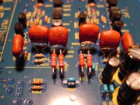
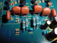
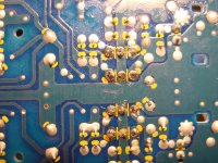
Thanks for this helpful instruction, the parts came from Mouser Electronics - Electronic Component Distributor and now the 8001 is working wonderfully again. The JFETs had to be turned around and leads 1-2 swapped. I decided to go with 2.2K ohm resistors instead of the original 1.2K ohm DAC couplers. This is so I can use the unit with some older amps without it distorting. So far, the sounds is as good as I remember it and without any distortion whatsoever. Thanks again for guiding a good fix, now documented for others. The light blue resistors are the 2.2K ohm metal film DAC couplers.
Attachments
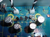
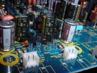
Very happy to help. Now all you need to do is get rid of all those horrid Elna caps before they start leaking & corroding the hell out of your board. You probably still have a few years before the leakage starts, but you never know. If you do replace them, use Nichicons if you want the unit to last, and sound good.
Oh, and if any of those Elnas are Duorex model series, I would replace them immediately!
Oh, and if any of those Elnas are Duorex model series, I would replace them immediately!
I forgot to turn the CD player off while I swapped in the tube amp today (the amps were off). The right channel is now distorted and softer than the left channel. I guess it did not like the swap. Changed cables and turned it off a few times. I think the JFETs on the right got damaged. This has to be one of the most fickle CD players I have ever owned.
Back to the bench
Back to the bench
I can't think of any likely scenario where doing what you did would cause any damage to the player circuitry. I certainly can't imagine it damaging any of those K170 fets. Although it looks like a pretty sound design, if the final output stage is borderline-stable, I could see one of the output transistors failing, or some other nearby component. I would do a dc voltage check at the junction of the final 2SC2240/2SA970 output transistor pair. If you find significant dc voltage, then the offset would be causing assymetrical clipping, and the indication would be a damaged component or two in the stage. I would advise, in any case, replacing these output transistors with 2SC2235/2SA965, for the sake of reliability and current capability.
Thanks for the guidance. Yes, the tube amp am sure had somethig to do with it. Often, I can feel some stray electicity when I touch its chassis, so I am sure something discharged through the RCA cable. At least I can just change the JFETs for starters. In the future, I will be more careful. I also will check for DC and consider changing those trannies.
Even after the fix, it poped at the end of CD or upon eject. Whereas before it popped all the time, like between tracks.
Even after the fix, it poped at the end of CD or upon eject. Whereas before it popped all the time, like between tracks.
- Status
- This old topic is closed. If you want to reopen this topic, contact a moderator using the "Report Post" button.
- Home
- Source & Line
- Digital Source
- Marantz SA8001 Modification to Eliminate Distortion