The receiver on the player must be faulty, as the remote has tested successfully on another unit. The schematic seems to not be available, but I could probably figure things out as I go along. Where should I begin and what measurements should I take to narrow this thing down?
The receiver is almost certain to be an off the shelf 3 pin type. Check for 5 volts, ground and use a scope to confirm the data stream when a button is pressed.
HERO|HIM602H|PHOTODIODE, IR RECEIVER, HORIZONTAL | CPC From This Range&MER=e-bb45-00001003
Is there an option to "turn off" the remote via software/front panel button press sequence etc ? you just never know these days. If you haven't a 'scope a DVM might show some voltage change on the output pin as a button is pressed.
It appears Cambridge units use the TSOP18 photo module, same deal. It's going to be fund getting that panel off. I've also discovered the player cannot read the first track, tries then skips to #2, from which point it seems to work fine. The laser is the KSS-213C. I'll re-seat the ribbon cable when I get back to it.
I've got the thing apart. I'm measuring supply voltage of 4.85V. At idle, the output is about .100mv and does respond to pressing buttons on the remote, reads out around .340 mv. In pressing different buttons (play, rew, etc), I get very similar readings in the vicinity of .340mv, I'm using a multimeter, hard to tell if they are really different though. I'm at a bit of a loss, I was expecting there to be no output and/or a fixed output that does not respond to the remote, but that is not the case.
I did test the remote at the diode and it appeared to produce noticeably different output voltage when pressing different buttons, though I can't recall the values, something around .700mv or so. I did learn a trick, though, to see if the remote was producing output, looking through the viewfinder of a digital camera, does work.
The part number of the little board holding the photodiode on the player is AP10716/1. The photodiode was shielded and I did not want to remove the shielding to get at the photodiode identifier.
The TSOP18 is a complete receiver... these things are all basically the same, with main differences being in the centre carrier frequency filter within the receiver.
Your readings could well be OK... the output of the receiver is a series of high speed pulses of 0 to 5 volt approx which DVM's won't read correctly... they just give an indication.
.
If you have any other RC devices you can measure the output from the receivers on those to compare.
http://www.datasheetcatalog.org/datasheet/vishay/82143.pdf
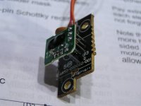
Well I went ahead and removed the module's shielding, does not look like a TSOP18. I had gotten that info from another CA schematic. Is this a custom module? There is no info on the diode board itself, but the lower board has the following markings:
HF-03
94V0
4850-010080-001
AP10716/1
I might as well replace the board and see what happens, perhaps things have drifted a bit. The cap's esr is about 3 ohms and measures 42uf (47uf/6.3V), the esr is slightly higher than expected of 1 ohm, but probably not enough to be concerned about.
HF-03
94V0
4850-010080-001
AP10716/1
I might as well replace the board and see what happens, perhaps things have drifted a bit. The cap's esr is about 3 ohms and measures 42uf (47uf/6.3V), the esr is slightly higher than expected of 1 ohm, but probably not enough to be concerned about.
Attachments
Not seen one exactly like that, however any standard type should work OK... if it's faulty, it may not be of course. You need to know the carrier frequency... if it's near enough it probably will work OK.
The supply will be across the electroylitic, and the wire that's left is the output.
A 'scope check is absolutely conclusive.
The supply will be across the electroylitic, and the wire that's left is the output.
A 'scope check is absolutely conclusive.
I can only find the service manual for the 640C and it does not identify the TSOP18 part enough to determine the carrier frequency. AP Part Number PY054. Anything here to indicate what the carrier frequency would be for mine? I'm guessing manufacturers would use the same carrier frequency to ensure interoperability of remotes?
- Status
- This old topic is closed. If you want to reopen this topic, contact a moderator using the "Report Post" button.
- Home
- Source & Line
- Digital Source
- Cambridge D500SE CD- No response to remote