I thought I'd do a brief guide on changing this as a couple of people have asked me about it when I mentioned it in another thread. It's very easy to do and the gear and belt are available on Ebay at the time of writing for about £12GBP. The player shown is a Marantz CD52, but the CD42 is the same and probably the CD32 too.
Step One: Remove the four side screws on the case lid (Philips-drive screws)
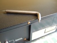
Step Two: Remove the T10 Torx screw from rear of case lid
Step Three: Remove lid
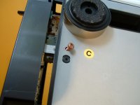
Step Four: Fold back disc clamp flap
Step Five: Remove spring from flap
Step One: Remove the four side screws on the case lid (Philips-drive screws)
Step Two: Remove the T10 Torx screw from rear of case lid
Step Three: Remove lid
Step Four: Fold back disc clamp flap
Step Five: Remove spring from flap
Attachments

Last edited:
...continued...
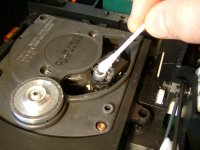
Step Six: Remove the 3 torx screws from the front panel
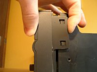
Step Seven: Unclip the front panel from the sides of the main chassis
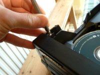
Step Eight: Remove the torx screw from the underside of the chassis at the headphone socket end
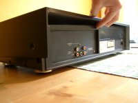
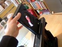
Step Nine: With the player resting on its back, pull the face-plate slightly forward and carefully withdraw the tray. It doesn't need to be forced.
Step Ten: Return the player to its normal upright position
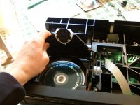
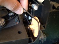
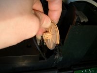
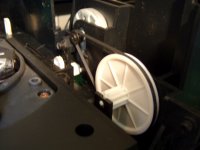
Step Eleven: Remove the old belt and tray/draw cog
Step Six: Remove the 3 torx screws from the front panel
Step Seven: Unclip the front panel from the sides of the main chassis
Step Eight: Remove the torx screw from the underside of the chassis at the headphone socket end
Step Nine: With the player resting on its back, pull the face-plate slightly forward and carefully withdraw the tray. It doesn't need to be forced.
Step Ten: Return the player to its normal upright position
Step Eleven: Remove the old belt and tray/draw cog
Attachments
...final part.
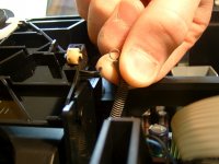
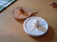
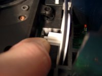
Step Twelve: Check the part against the new one and insert the new cog after placing the belt around it and the motor pulley
Step Thirteen: Clean the lens with pure alcohol and a cotton swab whilst you're in there (if you've never done this before)
Step Fourteen: Reinsert tray, clip the front panel back on and put the lid and all screws back as you found them.
Done!
I hope this is useful.
Simon
Attachments
thanks Man!
thanks Man!! I just fixed my cd52. I took the gear from a magnavox CD610. I will replace that one later. 🙂
thanks Man!! I just fixed my cd52. I took the gear from a magnavox CD610. I will replace that one later. 🙂
Thanks! Owner of a CD 52, waiting for the replacement parts to arrive. Your guide will be very useful!
Last edited:
Just replaced the cog and belt on my (20-ish year old) CD42 with parts bought off eBay for under 8 quid. Never done this type of repair before; the guide was really helpful - did it in under half an hour. Thank you!
Thanks Simon, I just fixed my 1992 Marantz CD42. It was easy, but only because of your comprehensive instructions.
CD-52 laser and focus adj without test discA?
@SimontY, many thanks for documenting the process, its still being used. Pity you do not get royalties, I would have been happy to pitch in.
My story, I have just purchased a dead CD52 for restoration and tweaking.
Quick check showed lots of litter from the broken gear wheel as I expected. I have since bought a replacement wheel and belt from Marcmart in HK on eBay.
Unfortunately I also found that someone had been inside it before me, to the point of removing the main board. Nothing was changed thankfully. However, when this moron put it back together he inserted PCB mounting screws into the holes for the laser and focus trim-pots, tightened them until the trim-pot end stop broke, jamming the screw in the hole. (now I know why 2 cover screws were missing).
I have the service manual which describes the fairly simple adjustment process.
But, do I need to acquire the test CD 5A? Does anyone have experience with laser current adjust and focus offset adjust without the test disc, are there any tricks?
Many thanks in advance....
John
Hi John,
I adjusted the laser current on a similar player once and I had no specific test disc. I think I just used normal music... no tricks or tips as I can't remember a whole lot about it, I just followed the instructions and it seemed to work ok.
I'm glad the guide is useful 🙂
Simon
I adjusted the laser current on a similar player once and I had no specific test disc. I think I just used normal music... no tricks or tips as I can't remember a whole lot about it, I just followed the instructions and it seemed to work ok.
I'm glad the guide is useful 🙂
Simon
Thanks Simon,
Have not tried the adjustments yet, i am stripping it down for a clean and tweak.
I decided to separate the 5 and 10 volt supplies by adding a small 20va toroidal mains transformer for the 5V digital needs and increasing the pre and post regulator filter capacitors along the way. Plan to use separate 78L05 regs for each of the 5 DAC power pins and a 7805 for the rest of the digital chain. Any other 5v can run off the existing supply thats shared with the servo. The 15v analog supplies will just get bigger caps and I have pulled the 5532's to replace with LME49720 but will DC couple the outputs. Then there's the oscillator and and and ..
Cheers
John

Hmm, good mods, it should sound really nice, especially if you re-clock it. There's always more isn't there?!
Simon
Simon
I found the low jitter vcxo from Vintage Audio Labs in Taiwan to do the reclocking, so thats now on order along with the caps and regulators and stuff. All due to arrive next week.
I have moved the existing fuses from transformer secondary to the primary side now that I will reduce the load on the existing transformer (surprising amount of heat marks on the inside of the top cover). There are pads on the main board for one mains fuse (was jumpered) so regrettably I will drill holes nearby for the second fuse to protect the second transformer.
That unfortunately gives me 240Vac wires running from the left hand side of the box to the vacant realestate on the right hand side. Can't see any way to avoid it.
And I have promised myself, that will be all.
Interesting stuff. I've had my eye on VALabs' gear on Ebay for a while... the clock, DACs and the stepped attenuators in particular.
Do let us know how the clock sounds in the '52!
Do let us know how the clock sounds in the '52!
Very happy with step 1. Gave it a good listening to then a service/clean/re-grease, re-adjusted laser current and focus after replacing all the power supply electrolytics, with a bit of a squeeze to miss the case work and each other.
the +/-15v smoothing were 100/35 are now 2200/35 FR
the +/- 10v were 1000/16 and 3300/16 are now 6800/16 HE
and 21 of the 47/25 scattered post regulator are now 470/25 ZLJ
the op amps are now LME49720 in sockets.
the bypass caps across the rectifier diodes replaced by snubbers on the secondaries, 100n+780R
Result is a remarkable reduction in noise and hiss and hum, its embarrassing how much because I thought it was pretty good before.
Really annoyed by the errors in the Marantz service manual - so many of the references do not line up with the CD52 that I could almost have cooked it.
Still waiting for the Vlab clock but have got my hands on some REG103/104's plus some LT3032's. Both have very good noise and load transient specs but the 3032's are far too small for my eyes. What was I thinking?
Last edited:
Outstanding! I do like the sound of these players, they can sing quite nicely, though I've not really gone to town on one. I may do one at some point, just for fun!
What brand of caps are FR, HE and ZLJ?
What brand of caps are FR, HE and ZLJ?
Oops, assumed you would know
FR = Panasonic, HE = Nichicon and ZLJ = Rubycon.
All 104C, high current (plus 0.8 or 1.0mm lead diam), long life and are tall, narrow with small pitch which makes them ideal for retrofit with much larger values.
I prefer FR and FC but they get expensive, and personally I think these are better than the Elna caps.
Tall, narrow and small pitch are awesome things as it's often so hard to squeeze in larger capacitance values!
- Status
- Not open for further replies.
- Home
- Source & Line
- Digital Source
- Replacing the draw cog and belt on CDM4/19 e.g. CD42/CD52