Now Fred almost agrees with me, that we get a squarewave.
However, if I get you right you are alternating between the
input values 0001 and FFFF so we have only two output values,
ie. a square wave, but the amplitude is "2 bits" pp (0001 - FFFF =
0002), ie. 1 bit peak, not 1/2 bit. To get the squarewave with
1/2 bit amplitude it seems we must add an offset to the signal
as SY suggested and as I used in my program that generated
such a squarewave. Well, now, what about larger amplitudes
than 1/2 bit? Do we still get a square wave? No, except for
signals of frequency 1/2 fs. Rather we do get at least three
distinct levels, as in the Stereophile diagram and in Steves
diagram. Well, I may be wrong, but this is my argument. It
is just a proof sketch, for the lack of time and a reasonable
way to write formulas (well, I could scan).
 Mathematics ahead!!
"Theorem": With 16 bits, we can represent sine waves with
real-valued amplitude arbitrarily close to, but not including
the value 20log(2^-16) dB (which is approximately -96 dB).
Proof sketch:
One error that I, at least, have made is to not really bother
about the case where the source has a value not corresponding
to any of the quantization levels. It seemed not necessary,
but of course it is.
Let's suppose our input signal is a sine wave of amplitude A
and with angular frequency w, that is Asin(wt). We restrict
A to be a real number s.t. 0<= A <= 32767. For every sample,
the real-number value of the function must be converted to
an integer in the interval -32767..+32767, which I assume
is most appropriately done by rounding off to the nearest
integer. (Note that we cannot use the value -32768 when
representing symmetric signals with no offset).
Now, let's look at input signals at and just above the amplitude
0.5, and write the amplitude on the form 0.5+x, where x >= 0.
Define this signal as the function f(x), that is
f(x) = (0.5+x)sin(wt) , where x >= 0
and let r(x) be f(x) rounded off to the nearest integer.
Now, consider the case x = 0.5, that is f(x) = f(0.5) = sin(wt),
that is r(0.5) will have the values -1, 0 and +1. In each cycle we
get a sample sequence of the form
0,...,0,1,...,1,0,...,0,-1,...,-1,0,...,0
that is, a signal of the form shown in Stereophile, or in Steves
diagrams. We have one positive pulse of amplitde 1 and one
negative pulse of value one. This is a "two-bit" peak to peak
signal corresponding to a sine at level 20log(2^-15) which is
approximately -90 dB. (I will round off all dB figures, not the
formulas, to enhance readability).
Then consider the case x = 0, which means f(x) = f(0) =
0.5sin(wt). Since the max and min values are 0.5 and -0.5 and
these get rounded off to 0, we get r(0) = 0, that is no signal at
all!!! Since f(0.5) = 2f(0), f(0) must be a sine at level
20log(2^-16) which is approximately -96 dB. So, this proves
that we cannot record down to -96 dB then?? No, not at all.
We have forgotten that the input signal can take on any
real-valued amplitude between 0.5 and 1, i.e. we can have
x values between 0 and 0.5 (and, of course larger too).
Now consider an arbitrary value of x, s.t. 0 < x < 0.5. Obviusly
the function r(x) will be of the alternating-sequence form
shown for f(0.5), but the positive and negative peaks will
be narrower, just as Steve showed in his diagrams. i won't
go into trivial calculus details here, but we note that as the
value of x decreases, the width of the pulses decreases (the
width can be expressed in intervals of angular frequency, in
time intervals or number of samples, though the latter case,
gives us a further quantization in the time domain).
To sum up, for arbitrary x > 0, r(x) will be a signal with one
positive peak of value one and one negative peak of value
one, and the remaining intervals of the cycle have the value
zero. The width of the pulses decreases as x approaches 0,
and the pulses disappear at x = 0. What does this mean?
Well, it seems to me to mean that we can represent the
function f(x) for all real values of x down to but not including 0.
We get the smallest representable sine wave as the limes
of f(x) when x approaches 0, and this corresponds to the
amplitude 20log(2^-16), since it is the amplitude of this limes
sine wave, although a signal
of exactly amplitude 20log(2^-16) cannot be repsented. So
there is a difference between -96 dB and -96 dB") The conclusion
The conclusion
would be that we can record sine waves with amplitude
down to, but not including -96dB (where 96 is a rounded off
value itself, to simplify).
However, if I get you right you are alternating between the
input values 0001 and FFFF so we have only two output values,
ie. a square wave, but the amplitude is "2 bits" pp (0001 - FFFF =
0002), ie. 1 bit peak, not 1/2 bit. To get the squarewave with
1/2 bit amplitude it seems we must add an offset to the signal
as SY suggested and as I used in my program that generated
such a squarewave. Well, now, what about larger amplitudes
than 1/2 bit? Do we still get a square wave? No, except for
signals of frequency 1/2 fs. Rather we do get at least three
distinct levels, as in the Stereophile diagram and in Steves
diagram. Well, I may be wrong, but this is my argument. It
is just a proof sketch, for the lack of time and a reasonable
way to write formulas (well, I could scan).
Mathematics ahead!! "Theorem": With 16 bits, we can represent sine waves with
real-valued amplitude arbitrarily close to, but not including
the value 20log(2^-16) dB (which is approximately -96 dB).
Proof sketch:
One error that I, at least, have made is to not really bother
about the case where the source has a value not corresponding
to any of the quantization levels. It seemed not necessary,
but of course it is.
Let's suppose our input signal is a sine wave of amplitude A
and with angular frequency w, that is Asin(wt). We restrict
A to be a real number s.t. 0<= A <= 32767. For every sample,
the real-number value of the function must be converted to
an integer in the interval -32767..+32767, which I assume
is most appropriately done by rounding off to the nearest
integer. (Note that we cannot use the value -32768 when
representing symmetric signals with no offset).
Now, let's look at input signals at and just above the amplitude
0.5, and write the amplitude on the form 0.5+x, where x >= 0.
Define this signal as the function f(x), that is
f(x) = (0.5+x)sin(wt) , where x >= 0
and let r(x) be f(x) rounded off to the nearest integer.
Now, consider the case x = 0.5, that is f(x) = f(0.5) = sin(wt),
that is r(0.5) will have the values -1, 0 and +1. In each cycle we
get a sample sequence of the form
0,...,0,1,...,1,0,...,0,-1,...,-1,0,...,0
that is, a signal of the form shown in Stereophile, or in Steves
diagrams. We have one positive pulse of amplitde 1 and one
negative pulse of value one. This is a "two-bit" peak to peak
signal corresponding to a sine at level 20log(2^-15) which is
approximately -90 dB. (I will round off all dB figures, not the
formulas, to enhance readability).
Then consider the case x = 0, which means f(x) = f(0) =
0.5sin(wt). Since the max and min values are 0.5 and -0.5 and
these get rounded off to 0, we get r(0) = 0, that is no signal at
all!!! Since f(0.5) = 2f(0), f(0) must be a sine at level
20log(2^-16) which is approximately -96 dB. So, this proves
that we cannot record down to -96 dB then?? No, not at all.
We have forgotten that the input signal can take on any
real-valued amplitude between 0.5 and 1, i.e. we can have
x values between 0 and 0.5 (and, of course larger too).
Now consider an arbitrary value of x, s.t. 0 < x < 0.5. Obviusly
the function r(x) will be of the alternating-sequence form
shown for f(0.5), but the positive and negative peaks will
be narrower, just as Steve showed in his diagrams. i won't
go into trivial calculus details here, but we note that as the
value of x decreases, the width of the pulses decreases (the
width can be expressed in intervals of angular frequency, in
time intervals or number of samples, though the latter case,
gives us a further quantization in the time domain).
To sum up, for arbitrary x > 0, r(x) will be a signal with one
positive peak of value one and one negative peak of value
one, and the remaining intervals of the cycle have the value
zero. The width of the pulses decreases as x approaches 0,
and the pulses disappear at x = 0. What does this mean?
Well, it seems to me to mean that we can represent the
function f(x) for all real values of x down to but not including 0.
We get the smallest representable sine wave as the limes
of f(x) when x approaches 0, and this corresponds to the
amplitude 20log(2^-16), since it is the amplitude of this limes
sine wave, although a signal
of exactly amplitude 20log(2^-16) cannot be repsented. So
there is a difference between -96 dB and -96 dB
The conclusionwould be that we can record sine waves with amplitude
down to, but not including -96dB (where 96 is a rounded off
value itself, to simplify).
Here we go again…
Pedja
Give me that file which will show peak amplitude -96.3dB (or any below -90.3dB). In any analyzer.RobM said:There are 65536 quantization steps, so LSB is 1/65536, or -96.33dB. Any other answer is wrong.

Pedja
Christer, "offset" is a term that offputs some people. You can equally well call it "asymmetry" (as I've said, people don't normally call a trumpet's waveform "offset"), or "scalar gauge," or a bunch of other things. The imposition of a symmetry requirement about an arbitrarily selected bit would trivially be seen to require three values, i.e., a two bit argument. But that imposition of symmetry was not a qualification of any of the original claims that are being discussed. The claims went to dynamic range (resolution) only.
Addendum to previous "theorem"
I should, perhaps comment on one assumption I made in
the "theorem" above.
I assumed that the smallest signal we can represent is the
smallest signal that does not get represented as a sequence
of all zeroes. That is, it is the smallest signal that does not get
completely lost in quantization error. One might argue that
we should, perhaps, have some requirement for reconstruction
also, but I think this is the right way to define it. As I have
said previously, no sine wave can be represented in PCM
and fully reconstructed, no matter what level it has, no matter
what number of bits we use, and I am assuming a theoretical
DAC and a theoretical LP filter. I need hardly say how much
harder it would be in practice. So, if requiring reconstruction,
beyong not being reconstructed as a DC level, we cannot
really have any firm levels and say what the smallest signal
is. We can only do so under some extra condition for the
reconstructed signal (eg. less than a certain amoung of THD
relative to the original signal), a condition that is not, to my
knowledge, included in any PCM standard and thus would
be an added requirement, not present in the original problem
formulation. Adding for instance a THD limit as condition, would
give us not one value for the dynamics, but an infinite number
of values of the dynamics, one for each possible value of
the max THD allowed.
SY said:Christer, "offset" is a term that offputs some people. You can equally well call it "asymmetry" (as I've said, people don't normally call a trumpet's waveform "offset"), or "scalar gauge," or a bunch of other things. The imposition of a symmetry requirement about an arbitrarily selected bit would trivially be seen to require three values, i.e., a two bit argument. But that imposition of symmetry was not a qualification of any of the original claims that are being discussed. The claims went to dynamic range (resolution) only.
Yes, I agree. I didn't mean we should not allow "offsets", I
merely pointed out that it was not necessary to add a 1/2-bit
offset as I did in my program, after your suggestion. We can
get down to the -96dB limit even with signals symmetric
around zero, which my "theorem" says. Not sure what result
we get if taking away that constraint too, but I guess (time
for somebody else to the maths this time
, that with offset we can get down to the value 20log(2^-16) inclusive, while
with symmetry around zero we can only
come arbitrarily close to it. A distinction that is of no importance
whatsoever to others than us who are amused by theory. In
practice it becomes -96 dB in both cases.
Re: Re: One, two, three... three or two, what do we need?
Pedja, assuming my maths is correct above, I would say it is
now clear that you will not get the correct answer from any
program. This would require the program to do the inverse
transformation from digital to analog domain (which is not
even possible for some data, the alternating unit sequence),
which would involve very heavy numerical computations
probably beyond what even a good PC today can do within
the time you are prepared to wait. I am sure the programs
just look at the actual digitalized samples and uses these
values as approximations.
RobM said:
There are 65536 quantization steps, so LSB is 1/65536, or -96.33dB. Any other answer is wrong.
Pedja, assuming my maths is correct above, I would say it is
now clear that you will not get the correct answer from any
program. This would require the program to do the inverse
transformation from digital to analog domain (which is not
even possible for some data, the alternating unit sequence),
which would involve very heavy numerical computations
probably beyond what even a good PC today can do within
the time you are prepared to wait. I am sure the programs
just look at the actual digitalized samples and uses these
values as approximations.
Re: Re: One, two, three... three or two, what do we need?
You look rather lonely there, Rob. Care for some company?
As they say, two heads are better than one.
se
RobM said:There are 65536 quantization steps, so LSB is 1/65536, or -96.33dB. Any other answer is wrong.
You look rather lonely there, Rob. Care for some company?
An externally hosted image should be here but it was not working when we last tested it.
As they say, two heads are better than one.
se

Re: two heads are better than one and two voltage levels are smaller than three
Hm, let's see, that's the "V sign", and V is roman 5, no that's too
many levels.
Fred Dieckmann said:The the number of possible DAC output voltage levels for the smallest possible output signal.
Hm, let's see, that's the "V sign", and V is roman 5, no that's too
many levels.

Maybe if we sing with Bing............
You've got to accentuate the positive
Eliminate the negative
Latch on to the affirmative
Don't mess with Mister In-Between
http://www.mathematik.uni-ulm.de/paul/lyrics/bingcrosby/accent~1.html
You've got to accentuate the positive
Eliminate the negative
Latch on to the affirmative
Don't mess with Mister In-Between
http://www.mathematik.uni-ulm.de/paul/lyrics/bingcrosby/accent~1.html
Attachments
Re: HAVING A FIELDDAY?
That the latest amp of yours, Frank? I can see valves on the
top.
fdegrove said:Hi,
Cheers,
That the latest amp of yours, Frank? I can see valves on the
top.
Hi,
Nope, a German "Kofferradio".
Let me assure you every bit is as important as the next in that one.
Cheers,
That the latest amp of yours, Frank? I can see valves on the top
Nope, a German "Kofferradio".
Let me assure you every bit is as important as the next in that one.
Cheers,
fdegrove said:Hi,
Nope, a German "Kofferradio".
Let me assure you every bit is as important as the next in that one.
Cheers,
I believe you and it seems to be four bits, counting the number
of valves. Maybe you can cascade four of them to 16 bits?
"Philosophers have argued for centuries about how many angels can dance on the head of a pin, but materialists have always known it depends on whether they are jitterbugging or dancing cheek to cheek"
"But 'glory' doesn't mean 'a nice knock-down argument,'" Alice objected.
"When I use a word," Humpty Dumpty said, in a rather scornful tone, "it means just what I choose it to mean – neither more nor less."
Today Humpty would write software; hardware engineers have always known the digital word zero doesn’t necessarily represent the analog voltage zero in any real ADC or DAC. But people do find it handy to use 2’s-complement and ignore the ½ lsb offset that comes along with dividing a symmetrical range into 2^^n-1 intervals. In fact “zero” in digital audio is often special cased in software and hardware allowing the distinction between a 0 level signal and “digital black” between valid data blocks.
If you choose to require that the digital code 0 to represent analog 0V and ask what is the smallest symmetric waveform amplitude then you get the 90 dB number that is causing so much consternation here
If you recognize that the most efficient use of your bits results in analog 0 volts being midway between 2 digital codes, the common 96 dB answer is about right for AC and consistent with the DC case where 96 dB is just right (for AC ½ lsb amplitude signal the amplitude of the fundamental of a square wave is ~ 2 dB higher than the square wave amplitude – this difference could be attributed to the correlation of the quantization noise which is causing further confusion and real distortion in the ½ lsb “sine” wave signal)
http://www.soundslogical.com/suppor...documentparts/resamplehelp-28.html#P403_35603
Which is Right? – I vote neither
If you want to move beyond pinheaded angel counting and address practical audible resolution and 16 bit word length issues you quickly discover that digital domain manipulation must be done at high bit resolution and dithering used to create the final 16 bit representation. Using dither and noise shaping, audible resolution in 16/44 CD digital audio can easily exceed 96 dB – with the greater advantages of sub-lsb linearity and decorrelation of quantization noise – only people shipwrecked on desert islands, working with bamboo and coconuts have any excuse to be limited to undithered or 16 bit resolution editing for even 16/44 mastering
(see next page in first link)
http://www.digido.com/ditheressay.html
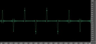
Rob M said:I also think everyone would agree that one could create a .wav file with only two sample values, giving an amplitude of -96dB with some DC offset. Yes? It's not especially easy to do that with cooledit, but all that tells us is that cooledit doesn't handle DC offsets very well.
Riiiiiight.....
Open Cool Edit. Create a new file, 44.1k, 16bit. Turn off dithering. Create a new wave with 50% DC offset, -6dBFS. Amplify it by -96dB. Zoom in, and you see a nice, but not perfectly symmetric, square wave with amplitude 1/2 LSB with a 1/2LSB DC offset.
I'd post the screengrabs, but it is really far too tedius.
Regards,
Mark Broker
mbroker said:...square wave with amplitude 1/2 LSB with a 1/2LSB DC offset.
You will never, never get signal, offset or anything written as 1/2LSB. I have never tried CoolEdit, but from the screenshots already posted here it is obvious it oversamples – why and how, by default or not, I do not have a clue and it is not important for now, but screenshots showed bigger resolution than those original files had. It is not hard to understand this way it can easily and happily move something up or down for the level that matches to the 16bit’s 1/2LSB. The point is that you’ll never, never save anything of it into the 16 bit file.
I have some wav files considering this… if I do not post it in the next hour it means I went to sleep, but will post them tomorrow.
Pedja
mbroker said:
Riiiiiight.....
Okay, let me revise that.
It's not especially easy for me to do that with cooledit, but all that tells us is that I don't handle DC offsets very well.
address practical audible resolution and 16 bit word length issues you quickly discover that digital domain manipulation must be done at high bit resolution and dithering used to create the final 16 bit representation. Using dither and noise shaping, audible resolution in 16/44 CD digital audio can easily exceed 96 dB – with the greater advantages of sub-lsb linearity and decorrelation of quantization noise
JCX,
Well Said!
Who was that masked man?
There has been a lot of talk here about PCM coding but no specific reference to a standard (AES, ISO, EBU, SMPTE, Sony, Phillips…) that identifies that specific binary values against specific specific voltage levels.
Digression:
[Back in the steam driven days of Digital audio processing I became perhaps a little too familiar withy a DAW built by some bright guys up in Boston. It had a 16 bit I/O but all the mix, DSP and other editing was performed on a 56 bit buss. The DSP had no less than 16 Motorola DSP 5600 chips on two VME cards.]
Attachments

- Status
- This old topic is closed. If you want to reopen this topic, contact a moderator using the "Report Post" button.
- Home
- Source & Line
- Digital Source
- The dynamic range of 16 bits