I got this parallel tda1541a DAC off ebay and have been playing with it for three weeks now. The DAC uses two parallel tda1541a chips. The I/V is a discrete current mirror circuit. Outputs from two tda1541a are wired directly to the I/V input
The DAC is working all fine with a single tda1541 in either of the socket. But when both tda1541 are plugged in, I can heard apparent noise/distortion - especially in the quieter music passages. The noise is not present when it is not playing music or it is between the gap of tracks. I switched different tda1541 chips in and out, some particular matches of tda1541 produce less noise, however it can not eliminate the noise completely.
This has led me to wonder if the I/V circuit is sensitive to matches of the tda1541a chips. Or two tda1541a may be in contention for bias current? Anybody has similar experience? Maybe each tda1541 need to be biased separately?
My guess: each output has a nominal current. Parallel them on the same load (that's 1/2 of the single version one) and one of them will be forced to output more current while the other less - because of the inherent small diffecences.
You should build different I/V stages and parallel the outputs.
If you kept the same I/V load, then both of them will be out of the nominal current range.
You should build different I/V stages and parallel the outputs.
If you kept the same I/V load, then both of them will be out of the nominal current range.
Last edited:
I recently fitted a pair of the new Burson Supreme V5 discrete op amps (duals) to my Sony 337ESD CD player which has parallel TDA1541 DACs and I'm getting exactly the problem described by pftrvlr. If I swap back to a 'normal' IC op amp such as JRC5532 or OPA2604 the problem disappears.
Any ideas?
Any ideas?
I got this parallel tda1541a DAC off ebay and have been playing with it for three weeks now. The DAC uses two parallel tda1541a chips. The I/V is a discrete current mirror circuit. Outputs from two tda1541a are wired directly to the I/V input
The DAC is working all fine with a single tda1541 in either of the socket. But when both tda1541 are plugged in, I can heard apparent noise/distortion - especially in the quieter music passages. The noise is not present when it is not playing music or it is between the gap of tracks. I switched different tda1541 chips in and out, some particular matches of tda1541 produce less noise, however it can not eliminate the noise completely.
This has led me to wonder if the I/V circuit is sensitive to matches of the tda1541a chips. Or two tda1541a may be in contention for bias current? Anybody has similar experience? Maybe each tda1541 need to be biased separately?
I also bought a parallel TDA1541 dac but rewired one to receive inverted data using a spare inverter on the board. In NOS mode with the SAA7220 removed, and using Sowter 9545 transformers and no other filtering or active devices between transformer and passive volume control. I am very happy with the results and of course, no noise issues.
The sound is much preferred over an Audio Note Dac1 (AD1865) and an ES9023 Sabre dac.
Perhaps you should try this method, although you will need a differential I/V stage or use transformers.
I no longer have the parallel tda1541a dac. Some of the things I did is here:
- Paralleled TDA1541 NOS/OS DAC -
I agree with betterman. Me too is big fan of transformer output. Currently my main DAC is a parallel ES9018 with transformer + resistor only output stage. I am so far happy. See here:
Dual ESS Sabre ES9018 DAC with Transformer Output ? Capstone Project
- Paralleled TDA1541 NOS/OS DAC -
I agree with betterman. Me too is big fan of transformer output. Currently my main DAC is a parallel ES9018 with transformer + resistor only output stage. I am so far happy. See here:
Dual ESS Sabre ES9018 DAC with Transformer Output ? Capstone Project
I no longer have the parallel tda1541a dac. Some of the things I did is here:
- Paralleled TDA1541 NOS/OS DAC -
I agree with betterman. Me too is big fan of transformer output. Currently my main DAC is a parallel ES9018 with transformer + resistor only output stage. I am so far happy. See here:
Dual ESS Sabre ES9018 DAC with Transformer Output ? Capstone Project
Yes I have the same issues now I have reconnected the dacs for parallel working.
However I noticed that pins 16 and 17 of the dacs, which are stated by Philips as not connected, are connected.
There is a 470pf cap on pin 16 to 0v so I am wondering whether the noise is due to differences in the oscillator frequency (nominally 200kHz)?
Might try a variable capacitor on one to see what happens.
(My I/V stage is an AD844 with 100r//10n on pin 5, capacitively coupled to an OPA627 buffer driving the transformer. )
Yes I have the same issues now I have reconnected the dacs for parallel working.
However I noticed that pins 16 and 17 of the dacs, which are stated by Philips as not connected, are connected.
There is a 470pf cap on pin 16 to 0v so I am wondering whether the noise is due to differences in the oscillator frequency (nominally 200kHz)?
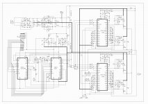
This is schema for //1541A DAC which works, I had one here maybe 10 years ago now. Note the arrangement with the cap across respective pins 16 &17, and with 16 on each chip shorted together at junction SYN (but you can try without this junction if you like)
470pF across each chip pin 16 & 17, short pin 16 of both chips together - and that is all (NO reference to 0V from pins 16 or 17)
LH/S
Attachments
Last edited:
This is schema for //1541A DAC which works, I had one here maybe 10 years ago now. Note the arrangement with the cap across respective pins 16 &17, and with 16 on each chip shorted together at junction SYN (but you can try without this junction if you like)
470pF across each chip pin 16 & 17, short pin 16 of both chips together - and that is all (NO reference to 0V from pins 16 or 17)
LH/S
Thanks I will try that.
The schematic I have shows the syn point on pin 16 on each dac but currently they are not connected to each other. There is a 470pf capacitor and I was incorrect to say it was connected to ground, it was indeed between pins 16 & 17.
I got these noise problems in NOS mode and never could get rid of it.
So I am using a digital filter now.
Did you try linking dac pin 16s?
Did you try linking dac pin 16s?
No I used only one TDA1541
Thanks I will try that.
The schematic I have shows the syn point on pin 16 on each dac but currently they are not connected to each other. There is a 470pf capacitor and I was incorrect to say it was connected to ground, it was indeed between pins 16 & 17.
Its probably a variation (looks the same to me) of the same DAC that I had (diyaudiocraft for google references) - and from the same place which is notorious for rip-offs.
Post back if it works, will help someone else later and further down the line..
LH/S
Its probably a variation (looks the same to me) of the same DAC that I had (diyaudiocraft for google references) - and from the same place which is notorious for rip-offs.
Post back if it works, will help someone else later and further down the line..
LH/S
Made no difference (didn't expect it to be that easy!) so now I will try dem reclocking both dacs from the same clock as per post 156 on:
http://www.diyaudio.com/forums/digital-line-level/11949-tda1541-dem-reclocking-16.html
The 11Mhz master clock is on board and supplies the Wm8805 which provides the other clocks so the dem reclocking will be synchronous.
I'm not sure if you're going about this the right way.
Using equal value 470pF capacitors and referencing pin 16 together with //1541A should work just fine - if not, your problem is not related to pins 16, 17 or the DEM circuit.
To confirm this is non-oversampling and neither pin 16 or 17 is referenced to 0V (you mentioned this before about 0V reference?)..
LH/S
I'm not sure if you're going about this the right way.
Using equal value 470pF capacitors and referencing pin 16 together with //1541A should work just fine - if not, your problem is not related to pins 16, 17 or the DEM circuit.
To confirm this is non-oversampling and neither pin 16 or 17 is referenced to 0V (you mentioned this before about 0V reference?)..
I also plan, at a later date, to take bck, lrck & data direct from the Wm8805 to the dacs, bypassing the 74F157 (U14) & HC125 (U12).
The signal level is about 3v, but according to ecdesign's, a lower level is beneficial. (I cannot find any specs for the 1541's I2S input requirements)
LH/S
I agree the noise & distortion when paralleling the dacs may have nothing to do with the oscillator. (yes using nos)
I removed the pcb and on the underside I found 2 smd resistors and caps connected to pin 16 on each dac. Pin 17 is connected to ground via a capacitor with no other connections.
Pin 16 is connected via 100pf to the Q3 output of a 74hc161 fed with 11.289Mhz from the master oscillator, via a 180r series resistor, with 470r to ground so there is already on board dem reclocking.
BUT, one dac has the resistors swapped and my research, mainly from ecdesign's posts, is that the internal oscillator has not been disabled so the reclocking is possibly not working very well and possibly not at all on one dac.
I will try using bck with ecdesign's 74hc00 with level shifters and 2k2 to -15v on pins 16 & 17 to disable the oscillator.
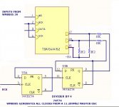
The schematic is attached, but does not show the extra components on pin 16.
Attachments
Last edited:
I agree the noise & distortion when paralleling the dacs may have nothing to do with the oscillator. (yes using nos)
I removed the pcb and on the underside I found 2 smd resistors and caps connected to pin 16 on each dac. Pin 17 is connected to ground via a capacitor with no other connections.
Pin 16 is connected via 100pf to the Q3 output of a 74hc161 fed with 11.289Mhz from the master oscillator, via a 180r series resistor, with 470r to ground so there is already on board dem reclocking.
BUT, one dac has the resistors swapped and my research, mainly from ecdesign's posts, is that the internal oscillator has not been disabled so the reclocking is possibly not working very well and possibly not at all on one dac.
I will try using bck with ecdesign's 74hc00 with level shifters and 2k2 to -15v on pins 16 & 17 to disable the oscillator.
The schematic is attached, but does not show the extra components on pin 16.
Attached is the alternative reclocking (& preferred) method borrowed (with the mistake corrected) from this thread:
http://www.diyaudio.com/forums/digital-line-level/11949-tda1541-dem-reclocking-21.html
Attachments
Ah.
I'd disconnect the whole lot. Try only a single 470pF across 16 & 17 on each chip and link pins 16 together.
This will tell you whether the problem lies with the DEM circuit as you have it - or whether the problem is elsewhere.
LH/S
Disconnecting all the components so 16 & 17 are not connected produced distortion for either dac (even worse when they were paralleled).
When I find some 470pf or 1n in series I will try again.
(However I might have fried the dacs because the 5v supply went down leaving the -5 and -15v supplies only, so not sure whether this might be the cause. )
I only had one 470pf cap but this has cured the distortion on one dac.
So with the new i/v conversion (AD844 + OPA627 driving transformers then direct to a passive preamp) , it is sounding not bad at all.
Without the cap the oscillator seemed to be around 999khz but with it , it is 200Khz, but seemed to varying from 196 to 207khz.
So the next step is to try the 74f74.
So with the new i/v conversion (AD844 + OPA627 driving transformers then direct to a passive preamp) , it is sounding not bad at all.
Without the cap the oscillator seemed to be around 999khz but with it , it is 200Khz, but seemed to varying from 196 to 207khz.
So the next step is to try the 74f74.
If I can suggest the next step is to find a pair of 470pF capacitors...
To be clear - one 470pF cap for each 1541A chip - and link pins 16 on each chip together - with no other connections to anywhere.. matched caps at 470pF will be best. This will have fDEM at 176kHz which is 4x the 44.1kHz sampling rate which is what you want.
Again - if it works it works, if it doesnt the problem is NOT with the DEM cct.
Once you get the parallel combination working, you have a benchmark and from there you can try other more elaborate DEM schemes knowing that any problem is resultant on the most recent change = very important.
_Go Trump!!_
LH/S
Last edited:
- Status
- This old topic is closed. If you want to reopen this topic, contact a moderator using the "Report Post" button.
- Home
- Source & Line
- Digital Source
- Parallel TDA1541A DAC Noise