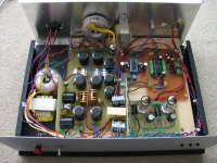
I mentioned before that I would be posting up pics of my dac and now I finally have the chance.
I started thinking and researching information for this DAC since early February and made a few attempts using a breadboard and then a PC board. These didn't work out too well so I decided to take it easy and just use a TDA1543 instead of the TDA1541A. This worked well but I found the sound to be not very refined. I was not satisfied and I was itching to see what the TDA1541A would sound like. So I tried again using a breadboard. I got all the power supplies tuned and popped in the IC.
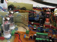
It sounded SO much better! The soundstage was wide, and the sound was smooth, very detailed and very much alive. It made the TDA1543 sound grainy and digital by comparison and it made the CD player built-in DAC sound like a transistor radio. Of course, I'm using a tube output stage based on ECC99s. I tried running these connected directly to the output of my CD player and it vastly improved the sound as well so I know that part of the way the DAC sounds is due to the tubes.
The DAC is quite good now that it seems to be able to position individual musicians in the soundstage. The speakers seem to disappear into the background.
I'm using a Sony SCD-775 SACD player. I converted the optical SPDIF out to a 75ohm BNC out.
My speakers are DIY jericho horns using Fostex FE-208 sigma full-range drivers. Sensitivity is >100dB/W/m..
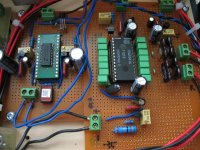
Power supply regulation is by LM317/337 and regulated on-board as close to the IC pins as possible using TL431s. Each power supply pin has its own TL431 regulator.
Tubes are DC heated to prevent 60Hz AC noise.
Mica caps are used at the DAC output for filtering... I used 2.5nF..
Analog and Digital grounds are joined by a ferrite bead.
I plan to add asynchronous reclocking as soon as I get some time.
I started thinking and researching information for this DAC since early February and made a few attempts using a breadboard and then a PC board. These didn't work out too well so I decided to take it easy and just use a TDA1543 instead of the TDA1541A. This worked well but I found the sound to be not very refined. I was not satisfied and I was itching to see what the TDA1541A would sound like. So I tried again using a breadboard. I got all the power supplies tuned and popped in the IC.
It sounded SO much better! The soundstage was wide, and the sound was smooth, very detailed and very much alive. It made the TDA1543 sound grainy and digital by comparison and it made the CD player built-in DAC sound like a transistor radio. Of course, I'm using a tube output stage based on ECC99s. I tried running these connected directly to the output of my CD player and it vastly improved the sound as well so I know that part of the way the DAC sounds is due to the tubes.
The DAC is quite good now that it seems to be able to position individual musicians in the soundstage. The speakers seem to disappear into the background.
I'm using a Sony SCD-775 SACD player. I converted the optical SPDIF out to a 75ohm BNC out.
My speakers are DIY jericho horns using Fostex FE-208 sigma full-range drivers. Sensitivity is >100dB/W/m..
Power supply regulation is by LM317/337 and regulated on-board as close to the IC pins as possible using TL431s. Each power supply pin has its own TL431 regulator.
Tubes are DC heated to prevent 60Hz AC noise.
Mica caps are used at the DAC output for filtering... I used 2.5nF..
Analog and Digital grounds are joined by a ferrite bead.
I plan to add asynchronous reclocking as soon as I get some time.
Attachments
Nice DAC you have. I'm in a proccess of building a similar thing.
I see you are using Schott input transformer from Digi-Key. I was experimenting with a similar one (S0109) in my Burr Brown based DAC and didn't like it. I found out that MIT RTX 0.01u sound much better. Do you have by any chance part number for CS8414 adaptor board?
I see you are using Schott input transformer from Digi-Key. I was experimenting with a similar one (S0109) in my Burr Brown based DAC and didn't like it. I found out that MIT RTX 0.01u sound much better. Do you have by any chance part number for CS8414 adaptor board?
Hi Peter
The 28 pin SOIC adapter is from browndog:
http://brndog.com/so28.html
Their prices seem more reasonable but they are a little slow to deliver..
BTW.. where did you get the MIT transformer?
The 28 pin SOIC adapter is from browndog:
http://brndog.com/so28.html
Their prices seem more reasonable but they are a little slow to deliver..
BTW.. where did you get the MIT transformer?
 LMAO...hahahaha
MIT are Multicaps from Partsconnexion, I'm not using transformer as I couldn't find a good one. This suppose to be a better one: http://www.scientificonversion.com/digital_audio.html
Are you using these MIT caps for decoupling? I was using solen 0.1uF tin foil caps at first but because of their size, I could not place them close enough to the pins. I saw that people were using small film caps so that's that I decided to use as well. I guess this is a compromise but I figured it's probably better to have the caps closer to the DAC than use exotic caps that are large, need to be placed further away, and pick up surrounding noise.
Very nice. Do you have a schematic for the tube stage? I'm not a tube guy so I'm curious.
I wouldn't bother changing the pulse transformer. It looks like you have two long solid core wires carrying the digital signal to the transformer. Switching to coaxial would be the first point of improvement.
I wouldn't bother changing the pulse transformer. It looks like you have two long solid core wires carrying the digital signal to the transformer. Switching to coaxial would be the first point of improvement.
This is how I do decoupling at IC's pins http://www.diyaudio.com/forums/showthread.php?s=&threadid=6232&highlight=mods+never+end Since I ave a lot of Panasonic 200u HFQ caps, I'm mostly using them, also BG N in certain locations.
As to the transformer and type of capacitors used at the receiver's input, I'd heard sonic differences depending on quality of parts used. But that transformer definitely wasn't my first choice.
As to the transformer and type of capacitors used at the receiver's input, I'd heard sonic differences depending on quality of parts used. But that transformer definitely wasn't my first choice.
jwb:
I've attached what I used for the tube stage below.. It's from Thorsten's Adagio dac schematic...
I just used a different type of tube.
I agree that I should change the signal wires to coax.. they're been bugging me but I wasn't sure what to do about them..
Peter:
That's a very cool way of decoupling!
I chose to use a pulse transformer because it's recommended in the CS8414 datasheet as the "professional" configuration.. so I assumed it must be better than the "consumer" configuration.. So if you're having good results with caps, then I will give them a try too!
")
I've attached what I used for the tube stage below.. It's from Thorsten's Adagio dac schematic...
I just used a different type of tube.
I agree that I should change the signal wires to coax.. they're been bugging me but I wasn't sure what to do about them..
Peter:
That's a very cool way of decoupling!
I chose to use a pulse transformer because it's recommended in the CS8414 datasheet as the "professional" configuration.. so I assumed it must be better than the "consumer" configuration.. So if you're having good results with caps, then I will give them a try too!
Attachments
Banned
Joined 2002
Although not the same, but similar project can be seen here: http://www.fortunecity.com/rivendell/xentar/1179/projects/adagio/Adagio.html
thanks Peter. Yes, Thorsten's Adagio is the basis of my design. I started with the schematic on this page:
http://www.ndh.net/home/kboehm/T-DAC-P1.htm
and just tweaked it a bit for the power supplies. I don't really have any schematics. I kind of just played it by ear. It's close enough to the above page though. I did not use the same values for the TL431 resistors though. Using his values require high wattage resistors. I fried a couple of resistors before I figured this out.
When building a DAC like this, the first step is to get the TL431 regulators producing the correct voltage while applying a load that approximates the current drawn by the ICs.. Once you get those, connect the FSYNC, SCK, SDATA pins from the CS8414 to the TDA1541, stick in an I/V resistor to ground (I used 68 ohms) and filter with 2.5nF silver mica caps and connect to tube output stage...
I did not use the TM-3 Amplimo signal transformer although i bought these.
From my experience, once you get the power supplies working, it's smooth sailing from there..
Test the tube output stage by itself prior to connecting to the DAC because it's hard to diagnose humming or other issues if you don't know if it's from the DAC or the tubes..
Digital/Analog supplies/grounds for the TDA1541A are as follows:
+/-5V are digital and correspond to digital ground..
-15V is analog and correspond to analog ground..
The schematic has an error on pins 17,18, 23, 24 on CS8414. You need to set I2S output mode and it's done like this:
pin 24: +5V
pin 23: DGND
pin 18: DGND
pin 17: DGND
Pins 16/17 on the TDA1541A require the 470p cap for proper operation of the internal oscillator.
My power supply was kind of crazy... I have a high voltage supply which is from the above site.. I had a -18V and +10V low voltage supply regulated by LM317/337... the -18V side is partly passed to a TL431 for regulation to -15V for the TDA1541A and to another LM337 for regulation to -10V. This then goes to two TL431s for the two -5V required by the CS8414 and the TDA.. The +10 just goes straight to two TL431s to make +5 for the two ICs..
The 6X4 rectifier has its own 6V transformer and the ECC99s have a separate regulator board which uses a 7812 regulator..
The site above shows diode rectification before the 6X4.. I eliminated this and just connected up the 6X4 as it's usually done..
I can't think of much more.. It's late now..


- Status
- This old topic is closed. If you want to reopen this topic, contact a moderator using the "Report Post" button.
- Home
- Source & Line
- Digital Source
- Pics of my TDA1541A/CS8414 tube dac