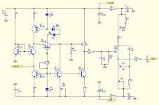
Got this schematic with the kit from Ebay, and need some help to understand the circuit.
First is regarding VR1 and VR2. Is VR1 to adjust the gain of IV, the voltage at AD1865 out to be 0v, or the voltage at R9 to be 0? I assume VR2 is to adjust quiescent v at R14 to 0, right?
Second is that the gain of the I/V is kind of low, how the gain is set in the circuit if it is not by VR1?
Thanks
Attachments
Got this schematic with the kit from Ebay, and need some help to understand the circuit.
First is regarding VR1 and VR2. Is VR1 to adjust the gain of IV, the voltage at AD1865 out to be 0v, or the voltage at R9 to be 0? I assume VR2 is to adjust quiescent v at R14 to 0, right?
Second is that the gain of the I/V is kind of low, how the gain is set in the circuit if it is not by VR1?
Thanks
Gain? There is no gain. It's a CB CB amp. CD is short for common base. R-IV is the 560 Ohm. For the rest it are all followers.
Kind of variation on Jocko's IV.
Q1 assures that the emitter of Q2 is at ground potential.
Last edited:
pftrvlr, can you post up the link for this Ebay seller, as I'm always up for trying out different Transimpedance I/V stages, the only thing I don't like at a quick glance about this one, is that the output is capacitor coupled, maybe this can be omitted if any dc offset that is there and can be trimed out somehow.
Cheers George
Cheers George
The kit is here
DAC kit AD1865N-K NOS 1.0 NOS - eBay (item 220530564349 end time Jan-01-10 22:25:35 PST)
I have removed the output capacitors and are able to adjust the DC offset to near a few mv. But the output offset drifts a lot, I ended up putting in two big 10uf MKP cap. Not all caps sound bad.
This is a smooth sounding DAC. Yet it is too smooth and not all the details come through. Not sure this is due to AD1865 or other parts of the circuit - especially the I/V.
I have removed the output capacitors and are able to adjust the DC offset to near a few mv. But the output offset drifts a lot, I ended up putting in two big 10uf MKP cap. Not all caps sound bad.
.
Try thermally coupling the input devices with a common heatsink, this is what I did with the Zap I/V and it drastically reduces the dc drift on the output, just touch them with your finger while monitoring the output dc and you'll soon see which are the ones are the offenders and need thermal control with each other as the dc will go negative with one and positive with the other, and the best sounding coupling cap is NO coupling cap.
Cheers George
Sorry to dig up this old thread. I also bought the same DAC as pftrvlr.
I have remove the output caps. The DC offset now measure at about 200 to 300mv. How to trim the DC offset? Using VR1 or VR2? Which point should I measure the original voltage for VR1 and VR2 before I start trimming so that I can revert back when I mess things up.
I have remove the output caps. The DC offset now measure at about 200 to 300mv. How to trim the DC offset? Using VR1 or VR2? Which point should I measure the original voltage for VR1 and VR2 before I start trimming so that I can revert back when I mess things up.
Sorry to dig up this old thread. I also bought the same DAC as pftrvlr.
I have remove the output caps. The DC offset now measure at about 200 to 300mv. How to trim the DC offset? Using VR1 or VR2? Which point should I measure the original voltage for VR1 and VR2 before I start trimming so that I can revert back when I mess things up.
You would adjust VR1. VR2 is there only to set the bias current of the output stage, and would have only a minor affect on D.C. offset. You will want to re-trim the D.C. offset after the circuits reach stable operating temperature - after about an hour or so.
Last edited:
I am also using this dac, but with a resistor as the passive i/v stage directly from the ad1865 chip.
The dc offset I get is about 3 or 4 millivolts. Is this safe to run directly into a power amp (I have a volume pot on my power amp)?
3 or 4 millivolts is very safe but how is the SQ with the DOS bypass? What is the value of the resistor u r using?
I'm using 560R resistors (I read somewhere that > 500R gives lower distortion) - the sound is phenomenal, best I've heard - all that is in the signal path is the transport, dac and amp (w/pot). I re-measured the dc offset last night after an hour of playing, and the drift was not much at all - each channel measured 2.7mv and 3.8mv. I don't even think I need a capacitor for filtering!
btw, what is DOS?
btw, what is DOS?
I'm using 560R resistors (I read somewhere that > 500R gives lower distortion) - the sound is phenomenal, best I've heard - all that is in the signal path is the transport, dac and amp (w/pot). I re-measured the dc offset last night after an hour of playing, and the drift was not much at all - each channel measured 2.7mv and 3.8mv. I don't even think I need a capacitor for filtering!
btw, what is DOS?
DOS = Discrete Output Stage
I find that the DOS is nice sounding with a quiet background although I have not tried to bypass the DOS yet. What is it that you don't like with the DOS? Most AD1865 sounds better with tube or DOS as the I/V stage.
In my opinion, the following mods really make significant improvement to the overall SQ.
1) Change the AD1865 chip
When I replaced the AD1865 chip, the treble open up and sound sweeter on the high notes thus leading me to believe the original chip is a fake. Look at the picture below, the genuine AD1865 on the left and the original AD1865 on the right. The pins on the genuine chip are made of better quality material and it has 3 dimple on the top and 2 below.
An externally hosted image should be here but it was not working when we last tested it.
An externally hosted image should be here but it was not working when we last tested it.
2) Bypass 26C32chip and implement the SPDIF input as per CS8414 datasheet
An externally hosted image should be here but it was not working when we last tested it.
3) Replace the resistor and cap value on pin 20 of CS8414 to 470R and 0.068uf as recommended by datasheet.
4) Mod L6 to tap power from +5VB as it is not in use to isolate the sharing of power for 74HC02 and AD1865
5) Bypass the 2 output caps on the DOS
Yep - I replaced the AD1865 chip and definitely noticed the difference. The original may be a fake. If it is - it's a good one!
I bypassed the DOS because my power amp is a push pull tube amp, so I think that adding another gain stage in between the passive i/v stage and the power amp would just be coloring the sound unnecessarily (correct me if I'm wrong).
The DOS sound fine, fantastic in fact - but when I put in the audionote resistors and forgot about the SRPP preamp I had in between the dac and the power amp, I found a much more honest sound.
The other mods you list there look great - don't think I've seen anyone else do them on the web. Which one do you think is the best to start with (aside from (5) which is n/a for me)?
Did you change the 16 diodes? I changed to motorola mur120 and it was certainly a step up....
I would suggest to start with 2 follow by 3 and 4 with the most significant first.
The mod get better of me and I lost control and change every cap except for the 4 power reservoir cap to see any significant improvement. I am still very tempted to upgrade the 4 power cap and 16 diodes but fear that the SQ improvement is minimal.
Another cheap option is to bypass the existing 16 fast recovery diode with 0.1uf cap. Anyone experience improvement with this method?
I am about to start working on this kit, too. Does anyone have a schematic for it that you could PM me? I bought it used, so it doesn't have one.
Also, what are the requirements for the power supply? The toroidal transformer that comes with it has 2 x 9v and 2 x 18v at 50 VA. I think it needs +5 for both the dac chip and the recieving chip, according to the article that Lampizator guy did on modding this board. The 2 x 18 (or 17?) are for the DOS. I may replace that with my Transendent Sound grounded grid tube preamp, using it as the gain stage after the resistor IV conversion.
Last question: I want to get a EI transformer or maybe a R-core (because the Rs are cheaper), recommendations. I've seen the R-cores on Ebay, and I'm looking for cheaper and better alternatives. Pipe dream?
I upgraded the power caps to 22,000uF caps, no real difference noticed there, but changing the diodes made a difference to to the resolution of the sound, for sure.
Why would this be an improvement?
**additional note - just changed the i/v resistors from 560R to 220R to get a little more gain. The dc offset has reduced from 3mv to 1.7mv. Why would this be? Could it be the capacitance of the resistors (they were a different brand).
Another cheap option is to bypass the existing 16 fast recovery diode with 0.1uf cap. Anyone experience improvement with this method?
Why would this be an improvement?
**additional note - just changed the i/v resistors from 560R to 220R to get a little more gain. The dc offset has reduced from 3mv to 1.7mv. Why would this be? Could it be the capacitance of the resistors (they were a different brand).
Last edited:
I am about to start working on this kit, too. Does anyone have a schematic for it that you could PM me? I bought it used, so it doesn't have one.
Also, what are the requirements for the power supply? The toroidal transformer that comes with it has 2 x 9v and 2 x 18v at 50 VA. I think it needs +5 for both the dac chip and the recieving chip, according to the article that Lampizator guy did on modding this board. The 2 x 18 (or 17?) are for the DOS. I may replace that with my Transendent Sound grounded grid tube preamp, using it as the gain stage after the resistor IV conversion.
Last question: I want to get a EI transformer or maybe a R-core (because the Rs are cheaper), recommendations. I've seen the R-cores on Ebay, and I'm looking for cheaper and better alternatives. Pipe dream?
You can DL the schematic from here
I woud prefer to use 2 x 12v and 2 x18v. The first stage of regulation for the 4 x 5v output is about 9.16v. It need about 3v difference for effective regulation. The first stage of regulation for 2 x 18v is for DOS and second stage for AD1865
Those R core are china made. Why don't spend a bit more for 2 x nuvotem toridal transformer
Why would this be an improvement?
There are 2 camp of thoughts here, one side say it remove floor noise while the other disagree
**additional note - just changed the i/v resistors from 560R to 220R to get a little more gain. The dc offset has reduced from 3mv to 1.7mv. Why would this be? Could it be the capacitance of the resistors (they were a different brand).
Correct me if I'm wrong, The AD1865 is using current output and the resistor convert it to voltage out so he value will have an impact on DC
Last edited:
- Status
- This old topic is closed. If you want to reopen this topic, contact a moderator using the "Report Post" button.
- Home
- Source & Line
- Digital Source
- AD1865 I/V Stage Help