Hi,
Since i have not so much time at the moment to work on my DAC project, i tried something which should require less time.
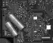
Got an old philips cd210 for free a few weeks ago and had a look inside:
- very basic machine: no remote, dig out or headphones
- cd-4 transport, SAA7310, SAA7220A, TDA1543 (strange: new decoder, old filter....?)
- very basic PS: one 7805 for all and no regulators for the opamps, just diodes and caps.
All in all a very basic machine, but easy to modify: PCB accessable from below without taking the player apart and the tracks stay on the pcb when you modify stuff. Good old belgian quality (lommel)..
Anyway, to try nos i did the following:
- remove 7220, replaced by three wires (i2s in -> i2s out) Maybe reclocking later, i have a 50MHz xtal waiting.
- move xtal from 7220 with r and c's to the 7310 (on top of it, close combat soldering..)
- connect mute on 7310 (was from micro to 7220)
- remove the analog output opamps and stuff.
- i only used spare and/or recovered parts, this is just to get a first impression on nos.
I then used the tracks for the pos. PS to the opamps to install a 7805 for the DAC. 5V looking good. I used thorstens schematic for a passive output for the TDA1543, also tried just a 1k resistor.
Well i got crap sound and found that the ref pin is not only attached to a resistor, but also to the opamps. Apperantly some feedback used there (?) Don't have the schematics, anyone out there who does have something for a philips machine with the mentioned chips (~1993) ?
Anyway, the resistor was 3k3 and i replaced it with 330 ohm and cut the trace to the opamp section.
Now the sound is better, but not good: it sounds distorted. When i look on my scope it looks like the neg half of the sin wave (from the test cd) is flattened. Like an amplifier clipping. However, my scope is very old (tube,1MHz,sixtees) and comes with free 50Hz wave with inputs shortened... I could be seeing things which are in the scope and not on the dac :->
Anybody have any idea's, already replace the TDA but no luck (so i have two good bad ones or two good ones, if this is fixed i can parallel them :->.
Thanx,
GuidoB
Since i have not so much time at the moment to work on my DAC project, i tried something which should require less time.
Got an old philips cd210 for free a few weeks ago and had a look inside:
- very basic machine: no remote, dig out or headphones
- cd-4 transport, SAA7310, SAA7220A, TDA1543 (strange: new decoder, old filter....?)
- very basic PS: one 7805 for all and no regulators for the opamps, just diodes and caps.
All in all a very basic machine, but easy to modify: PCB accessable from below without taking the player apart and the tracks stay on the pcb when you modify stuff. Good old belgian quality (lommel)..
Anyway, to try nos i did the following:
- remove 7220, replaced by three wires (i2s in -> i2s out) Maybe reclocking later, i have a 50MHz xtal waiting.
- move xtal from 7220 with r and c's to the 7310 (on top of it, close combat soldering..)
- connect mute on 7310 (was from micro to 7220)
- remove the analog output opamps and stuff.
- i only used spare and/or recovered parts, this is just to get a first impression on nos.
I then used the tracks for the pos. PS to the opamps to install a 7805 for the DAC. 5V looking good. I used thorstens schematic for a passive output for the TDA1543, also tried just a 1k resistor.
Well i got crap sound and found that the ref pin is not only attached to a resistor, but also to the opamps. Apperantly some feedback used there (?) Don't have the schematics, anyone out there who does have something for a philips machine with the mentioned chips (~1993) ?
Anyway, the resistor was 3k3 and i replaced it with 330 ohm and cut the trace to the opamp section.
Now the sound is better, but not good: it sounds distorted. When i look on my scope it looks like the neg half of the sin wave (from the test cd) is flattened. Like an amplifier clipping. However, my scope is very old (tube,1MHz,sixtees) and comes with free 50Hz wave with inputs shortened... I could be seeing things which are in the scope and not on the dac :->
Anybody have any idea's, already replace the TDA but no luck (so i have two good bad ones or two good ones, if this is fixed i can parallel them :->.
Thanx,
GuidoB
Nice experiment. And it seems like a ideal player to mess with. But why did you try 330 ohm??? 
Do a search for some configurations you can try and the theory behind it. Try 5V or 6V (better) with 3x1k resistor (2x for left/right, 1x for Vref resistor).
Or try 8V with 2x1.5k and 1x 1k...
Fedde
Do a search for some configurations you can try and the theory behind it. Try 5V or 6V (better) with 3x1k resistor (2x for left/right, 1x for Vref resistor).
Or try 8V with 2x1.5k and 1x 1k...
Fedde
guido said:Hi,
Since i have not so much time at the moment to work on my DAC project, i tried something which should require less time.
Got an old philips cd210 for free a few weeks ago and had a look inside:
- very basic machine: no remote, dig out or headphones
- cd-4 transport, SAA7310, SAA7220A, TDA1543 (strange: new decoder, old filter....?)
- very basic PS: one 7805 for all and no regulators for the opamps, just diodes and caps.
All in all a very basic machine, but easy to modify: PCB accessable from below without taking the player apart and the tracks stay on the pcb when you modify stuff. Good old belgian quality (lommel)..
Anyway, to try nos i did the following:
- remove 7220, replaced by three wires (i2s in -> i2s out) Maybe reclocking later, i have a 50MHz xtal waiting.
- move xtal from 7220 with r and c's to the 7310 (on top of it, close combat soldering..)
- connect mute on 7310 (was from micro to 7220)
- remove the analog output opamps and stuff.
- i only used spare and/or recovered parts, this is just to get a first impression on nos.
I then used the tracks for the pos. PS to the opamps to install a 7805 for the DAC. 5V looking good. I used thorstens schematic for a passive output for the TDA1543, also tried just a 1k resistor.
Well i got crap sound and found that the ref pin is not only attached to a resistor, but also to the opamps. Apperantly some feedback used there (?) Don't have the schematics, anyone out there who does have something for a philips machine with the mentioned chips (~1993) ?
Anyway, the resistor was 3k3 and i replaced it with 330 ohm and cut the trace to the opamp section.
Now the sound is better, but not good: it sounds distorted. When i look on my scope it looks like the neg half of the sin wave (from the test cd) is flattened. Like an amplifier clipping. However, my scope is very old (tube,1MHz,sixtees) and comes with free 50Hz wave with inputs shortened... I could be seeing things which are in the scope and not on the dac :->
Anybody have any idea's, already replace the TDA but no luck (so i have two good bad ones or two good ones, if this is fixed i can parallel them :->.
Thanx,
GuidoB
Hi GuidoB,
The opamp in your player is connected as a classic IV-converter just as in the datasheet of the TDA1543.
See http://www.semiconductors.philips.com/pip/TDA1543_CNV_2.html
and download the datasheet.
Vref is connected to the non-inverting input of the opamp and the current output of the DAC connected to the inverting input. Philips uses a 3k3 resistor form Vref to ground. The output of the opamp is connected through a 3k resistor to the inverting input. In one of my old Philips players a dual opamp is used and the second of the dual is the ouputbuffer. I would as a first experiment try only replacing the opamp by a OPA2604 f.a. if a dual is used probably LM833.
Fedde is referring to passive IV-conversion using no opamp at all but I was not too happy with the result.

I already removed the opamps, only using some passive components. Seems 330 is for 4 TDAs and 1k for only one.
I changed to 1k (had smd on stock).
Made one mistake with the outputs, fixed that. Still some distorsion. Then i removed the inductors: distorsion gone.
Seems they are not ok or the fact that i did not use a starground was the problem. Anyway, it is playing now and sound is quite good. I'll tweek more later..
GuidoB
PS, nobody has a servicemanual ???
Servicemanual
Hi Guido,
You can try
in Europe:
www.schaltungsdienst.de (Schaltungsdienst Lange) in Berlin.
Hi Guido,
You can try
in Europe:
www.schaltungsdienst.de (Schaltungsdienst Lange) in Berlin.
Guido, how is your CD210 modification catching on?
Today I bought a Philips CD210. Flea market. The output didn’t work.
The chipset is SAA7310, TDA1543 as DAC, two LM833 for filtering and signal output. The printed circuit is two sided, where one side is mainly earth. I read that SAA7310 seems to be giving superior error correction and that Meridian uses it for that reason
I did the following mods:
1) I disconnected the digital feed to the digital output, disconnected the two pins so now I have two extra cinch sets for output on the back.
2) I connected a 470nF capacitor to the pin 2 of the LM833 of each channel (the first opamp, like in the specs). This I did because I found no signal (strange) on pin 6/8 of the DAC (scope).
3) I also replaced the supply cap on the DAC (originally 220 muF) with a solid tantalum 150 muF and this really should have a good effect as these have linear response op to the Mhz (used by the former l’Audiophile team on all supplies). Solid tantalum from STC is a tubular design, 2 cm by 0,75 cm)
So everything else remains in place, including the inductor, they are just quite further on in the circuit.
This first opamp of the LM833 is used as a 40 kHz lowpass (1k2/3n3). So this is rather OK to tap off. The output impedance is low enough.
I compared this with my Meridian 206. I have one CD twice in my collection: Leclair - Sculla and Glaucus (Gardiner). This allows real double blind testing. There is no level difference between the two outputs.
The CD210 with this modification gives a definite better soundstage: just handling violins better on normal and heavy passages. Ease and relaxation. Pleasant. Convincing – also to my wife. It’s excellent. The 206 is a 1-bit. The impression I have on a CD like Sade Lovers Rock also shows that rock (intensely mixed) also sounds more relaxed. The bass is tighter. The sound effects and gimmicks come on clearly now. On Brassens Les copains d’abord the guitar is not anymore larger than life, really sounding like as they are his ‘les copains gonflés’ playing along.
The proof of the pudding is Cristina Branco, canta Slauerhoff, so well recorded by Eelco Grimm. Here we hear true, clean stage in all its variations of volume and naturality, instruments that are just are an accompaniment of a pure voice. No smearing at crescendo’s. The text of the spoken poem also is natural now.
This doesn’t mean the CD210 is better overall … the CD210 transport rather often jumps on a scratch or for whatever reason == it just mutes half a second.
Anyway, my experiment give ample thought to continue.
Probably make a separate DAC to capture my Meridian 206 output.
Still I feel my soundstage doesn’t have the quality (extreme depth) yet of the Dutch Radio4 classical FM broadcasts (that compares very favorably to for example BBC3). I remember having read the radio stations in Holland use special non-over sampling, non-error corrected CD drives. Leaves me wondering. Somewhere there must be a trick to all this.
Any tips?
So should I bypass the TDA7310 and have the set converted it to zero oversampling??? Who has experiences with this?
Just a correction of a mistake: I connected the output on pin 7 of the LM833's. I attach a picture.
See the place where I cut the output plugs, very simple job to do.
Thinking over it: I think that the outputs (6/8) of the TDA1543 are not giving off any trace is because they run into the feedbackloop of the LM833 opamp. So the internal resistance of the TDA1543 attaches to the feedback and this regulats untill there is just no signal left, any microvolt difference is ampolified. So the connection looks like it is plan earth on the scope but the opamp is doning the work to keep it like that and the by-product of this configuration (like a summing amplifier) is a clean output signal!
This is just another description of course of an inverting amplifier but I think its fits better here in this circumstance.
--> New next experiments might follow:
So next I might ..
- solder a second TDA1543 on top,
- take the pins 6,7,8 to 1 k resistors to the star ground and tap it off to output L,R
- might have to add a capacitor.
remark: Now if the resistor is only the I/V converter it can also be e.g. 560 ohm .
But I think that it will try to dump from the 2 volt output to earth: some 2-4 mA DC
- so it might need a capacitor in between? Who has experience in this?
and further:
- Should I insert that triode with a natural 40k first order slope?
albertK
Attachments
- Status
- This old topic is closed. If you want to reopen this topic, contact a moderator using the "Report Post" button.
- Home
- Source & Line
- Digital Source
- tda1543 problem