Hi,
I've been looking at the schematics of the Cambridge 740C CD player, but the circuit is similar in the in the 640C, 640CV2, 750C, and also the new Dacmagic which is what I have.
(Note I asked this already but it was buried in a Dacmagic thread.)
What is the purpose, or indeed benefit of this configuration of op-amps?
There's a kind of inverted output signal into the non-inverting input ground of the first op-amp.
I guess this is the "Dual Differential Virtual Earth balanced filter topology" they talk of their blurb. As though they are trying to create the same conditions for both phases of the differential DAC signals.
Does this configuration have a name? I have not seen it before.
Is the second op-amp considered to be in the signal path, or rather, is this more like a single op-amp application?
How much affect would the qualities of the second op-amp have?
I'm a bit confused as I've not seen anyone else do it this way.
Why is it better than the more usual grounding of the +ve signal (see edits in red).
Glenn
Attachments
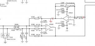
That's the negative feedback. Instead of applying the neg feedback only on one input in an assymetrical way, they take the output, invert it and apply the feedback on positive input too. In this way the main Op-Amp has symetrical signal and impedances on the inputs. Maybe hepls with interferences via ground since it will isolate the ground plane, but I didn't tested nothing like that.
I would use the second half of a dual OpAmp for that.
I would use the second half of a dual OpAmp for that.
Last edited:
I would use the second half of a dual OpAmp for that.
That's how they do it.
")
The second opamp keeps the output at zero volts DC. It's non inverting input is ground referenced
The output is ac-coupled though. Why bother?
(Although I've actually bypassed the output caps as they only block 1-3mV)
The output is ac-coupled though. Why bother?
(Although I've actually bypassed the output caps as they only block 1-3mV)
I can only see the circuit you have posted
can't see what comes next, muting etc.AC coupling is an industry fashion anyway, as a manufacturer you don't know what someone might connect it to. If you modded the circuit as you propose I think you would find significant and potentially damaging offset voltages at the output. The reason you only see 1 to 3 mv is because of the second opamp behaving like a servo.
Further thought... how does it mute ?
If it uses transistors these need to switch at zero volts or you will get a massive click when the muting operates.
And similarly if it uses relays too. You have to switch audio at zero volts DC and preferably at the zero crossing point in the signal for it to be totally silent.
Also only a few millivolts DC is needed to make a volume control "noisy" as you turn it, so if it were DC coupled with an offset and fed to a passive or DC coupled preamp that too would be a recipe for disaster.
If you want to decouple the opamp, a small 10mfd low esr cap soldered directly to pins 4 and 8 is best. Never add decoupling from supply to ground unless you are sure that any rail disturbances can not enter the signal ground. Rail to rail at the opamp pins is by far the best You could even add a smaller bypass cap of around 0.1mfd in series with a 1 ohm (to avoid creating any unwanted resonant peak with the self inductance of the 10 mfd)
I would love to hear how that design sounds with a different IC to the NE5532
If it were me I would try an OPA2604 FET input device which should be totally stable in that configuration.
You could even add a smaller bypass cap of around 0.1mfd in series with a 1 ohm (to avoid creating any unwanted resonant peak with the self inductance of the 10 mfd) I would love to hear how that design sounds with a different IC to the NE5532
If it were me I would try an OPA2604 FET input device which should be totally stable in that configuration.
There is no "servo" there. It is virtual ground and the DC voltage is almost zero per OpAmp equations for DC signal, but not zero since no integration it is done (like on a true DC servo). See PID theory.
Remove it and see what the DC offset is
Opamp theory (at a basic level) says the output of an opamp with feedback will do whatever is necessary to keep the DIFFERENCE in voltage between the inverting and non inverting inputs at zero.
The non inverting input is referenced to ground, the inverting input is taken from the "audio" output line so that too becomes zero. You don't need an integrator in that sense.
Further thought... how does it mute ?
If it uses transistors these need to switch at zero volts or you will get a massive click when the muting operates.
And similarly if it uses relays too. You have to switch audio at zero volts DC and preferably at the zero crossing point in the signal for it to be totally silent.
Also only a few millivolts DC is needed to make a volume control "noisy" as you turn it, so if it were DC coupled with an offset and fed to a passive or DC coupled preamp that too would be a recipe for disaster.
There's no clicking. The relays mute but only at power on/off.
I generally consider anything below 25mV to be OK. My amp is cap-coupled at input (ok, after voume pot) but the 20mV I get from my Marantz CD-63SE causes no huffing when I turn the volume. (By the way, that now has AD825, HDAM buffers bypassed, delayed relay muting on power, and no output caps, plus countless other mods.)
That's the negative feedback. Instead of applying the neg feedback only on one input in an assymetrical way, they take the output, invert it and apply the feedback on positive input too. In this way the main Op-Amp has symetrical signal and impedances on the inputs. Maybe hepls with interferences via ground since it will isolate the ground plane, but I didn't tested nothing like that.
I would use the second half of a dual OpAmp for that.
I must say, I don't know why, but this sounds more plausible than the servo theory.
I wonder if it helps common-mode distortion of the op-amp. I mean, without this the non-inverting input is outside the feedback loop (one of the reasons inverting configurations are preferred of course to non-inverting for unbalanced signals). Just a thought.
Last edited:
Try the LME49723 or the LME49725. The former is my favorite dual opamp in plastic package to date.
I've not tried these, but have tried the LM4562MA/HA and LME49710 singles in various applications. I didn't like them at all, sounding devoid of colour and emotion. There aren't many duals I do like but would probably go for AD8599 here as a first attempt. Maybe even OPA2132 to warm the balance slightly.
I've got the Dacmagic hooked up to a Zapfilter2 at the moment as well (in pieces on the floor) but I'm thinking it sounds almost too relaxed through that, unless I'm just too used to op-amps!
The LME49723 is my favorite since it has the transparency but it doesn't sound colorless.
The AD8599 may work well... but it's not one of the very low distortion opamps. Even an OPA2132P would result in less distortion.
You may use either the LT1028CS8 (two per socket) or the OPA1612...
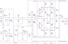
Question: why on earth add that discrete buffer stage to the output of the OPA2134???This is what I would expect to see for a servo. (HK HD970)

Minimize distorsions. Higher the output current, higher the TDH. That output drives headphones too.
The schematic is very simple and eliminates some problems.
Of course, it needs the intergrator...This is what I would expect to see for a servo. (HK HD970)
The schematic is very simple and eliminates some problems.
Last edited:
- Status
- This old topic is closed. If you want to reopen this topic, contact a moderator using the "Report Post" button.
- Home
- Source & Line
- Digital Source
- Op-amp circuit question (DAC o/p)