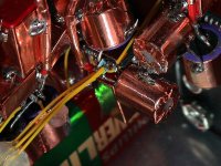
Thought this pic might amuse some of you and serve as inspiration for those who find getting pcb's an issue.....
The chip in the middle is a SSOP DF1704 and the yellow lines are DATA, BITCLOCK and LE. The blue things are 0603 smd resistors.
The copper shielded bigger caps are Oscon 100uF. Can't get them much closer then that.
Up in the right corner one can see some of the legs on the CS8420 also hardwired. Being a SOIC it is a so much easier to hardwire then the DF1704.
Attachments
Getting PCB's IS an issue !
It looks nice but nevertheless I prefer a PCB over it. Wire lengths are shorter and thus stray inductance/capacitance is lower. The ( recommended ) groundplane is possible on a PCB and reliability is higher too. Designing it and the time it takes are true drawbacks I have to admit.
I realise "productivity" when hardwiring is higher but I can not come loose from the feeling it is an easy way out skipping the tedious and more expensive PCB design stage ( for me that is ).
Respect for building it so compact and tidy. Your eyes probably are sore after doing a job like this")
Thought this pic might amuse some of you and serve as inspiration for those who find getting pcb's an issue.....
It looks nice but nevertheless I prefer a PCB over it. Wire lengths are shorter and thus stray inductance/capacitance is lower. The ( recommended ) groundplane is possible on a PCB and reliability is higher too. Designing it and the time it takes are true drawbacks I have to admit.
I realise "productivity" when hardwiring is higher but I can not come loose from the feeling it is an easy way out skipping the tedious and more expensive PCB design stage ( for me that is ).
Respect for building it so compact and tidy. Your eyes probably are sore after doing a job like this
Hey A 8. That is indeed a feat of SSOP construction. But I have to ask: where do you think the return path for those signals is?
You have the BCLK and DATA hanging out in free space. The rise time on the DF1704 is 2ns, so your effective system speed is 125MHz. At RF speeds the return path <em>wants</em> to be directly under the signal, but this is not possible here. So the return path is through the DAC chip, out the DGND pin, and via the power supply wiring all the way back to the DF1704. I think you could fairly call that loop area "huge". It's probably radiating all over the place.
I'm not picking on your work, which I say is a tremendous display of dexterity, but when the power is applied, I don't think the performance is going to be that hot.
Hi Guys,
Don't get me wrong, I would also prefer a pcb but as you know it is a lot of work to get it good. This way its easier to redo and tweak which in my case happens too often.
Wrt to ground planes and return paths I don't think it is that far off.
The ground goes right under the df1704 soldered on the copper shield and the DGND pin on the DF then out on the left side (3 mm off chip) of the chip where it pass through the clock circuit and onto the dacs ground. The df is slightly offset relative to the dacs so it works out ok in terms of lead length.
All the free air signals are in practice surrounded by copper shields, not ideal but not completely off.
It is actually only data and LE that comes out of the df, bit clock is derived directly from the master clock. The position of the df is a small compromise as I gave the clock circuit priority in terms of distance and return paths relative the dac chips.
wrt building it....It helps that I am a bit narrow sighted
I have issues with it but so far I think they are related to word lenghts and quantization noise.
I believe I need something on the input side to manage different sources and bit dephts.
When fed a 24/48 digital signal I am really impressed by it.
Jean-Paul,
I agree, it is bugging me.
I think it is easier keep wire lengths short as one has more spacial freedom.
The ( recommended ) groundplane is possible on a PCB and reliability is higher too.
I agree, it is bugging me.
Wire lengths are shorter and thus stray inductance/capacitance is lower.
I think it is easier keep wire lengths short as one has more spacial freedom.
- Status
- This old topic is closed. If you want to reopen this topic, contact a moderator using the "Report Post" button.