OK, here's some final bits of info that I've picked up about the HiFace before I mod it - please correct any point that you might think might be wrong:
Regulators:
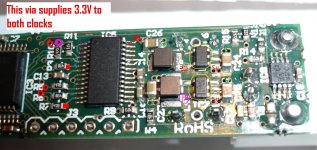
- These 3.3V & 1.8V chips are step down DC-DC converters TPS62203 which use a 1MHz fixed freq PWM for operation - I believe these have to go for best sound particularly as the 3.3V supplies both IO banks of CPLD with power as well as the clocks PS. The 1.8V is supplied to the CPLD's core. Pin 3 of these 5 legged chips is an enable pin which is enabled at high. It might be possible to lift this pin (very tight layout!) & connect to ground to disable these chips?
Clocks:
These are MEC clocks but I can't find a datasheet for these particular IDs. smd MEC clocks that I can get locally from Radionics have a jitter spec of 10ps (I know this single figure is almost meaningless but at least it's not 500ps") ). These clocks feed into pins 43 & 44 of the CPLD and MCLK is generated & output to the DIT4192 along with SDATA. So part of the CPLD is being used as a clock MUX & buffer - for best sound it's important to provide it with clean 3.3V & 1.8V supplies. The CPLD then outputs MCLK & SDATA to the DIT
). These clocks feed into pins 43 & 44 of the CPLD and MCLK is generated & output to the DIT4192 along with SDATA. So part of the CPLD is being used as a clock MUX & buffer - for best sound it's important to provide it with clean 3.3V & 1.8V supplies. The CPLD then outputs MCLK & SDATA to the DIT
DIT4192:
- requires 5V pin 19 so external 5V supply needed
- works at 128x for 176.4 and 192kHz speeds, 256x for 88.2 and 96kHz, 512x for 44.1 and 48kHz based on pins 4&5 (CLK0, CLK1) being set.
- it is operated in master mode based on pin 14 (M/S) set high? So both SYNC (R6) & SLCK (R5) are outputs
- operates in 24 bit I2S based on pin 9 (FMT0) is high & pin 10 (FMT1) is low
So here are the mods I intend & the stages of implementation:
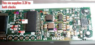
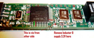
- Tap out I2S from the attached points in the pic (red points show the points for tapping the signals downstream from the resistors)- I'll be using short leads to a local DAC so I'm hoping I can arrange a plug-in connection for this DAC. I'll be listening to this configuration for a while to get an idea of the sound but knowing me I'll want to go straight to the next stage.
- Supply an external clean 5V supply in place of the USB 5V - evaluate
- Supply an external clean 3.3V supply to the two audio clocks - evaluate
- Supply a separate clean 3.3V supply to the CPLD - evaluate
- Supply a clean 1.8V supply to the CPLD - evaluate
Regulators:
- These 3.3V & 1.8V chips are step down DC-DC converters TPS62203 which use a 1MHz fixed freq PWM for operation - I believe these have to go for best sound particularly as the 3.3V supplies both IO banks of CPLD with power as well as the clocks PS. The 1.8V is supplied to the CPLD's core. Pin 3 of these 5 legged chips is an enable pin which is enabled at high. It might be possible to lift this pin (very tight layout!) & connect to ground to disable these chips?
Clocks:
These are MEC clocks but I can't find a datasheet for these particular IDs. smd MEC clocks that I can get locally from Radionics have a jitter spec of 10ps (I know this single figure is almost meaningless but at least it's not 500ps
). These clocks feed into pins 43 & 44 of the CPLD and MCLK is generated & output to the DIT4192 along with SDATA. So part of the CPLD is being used as a clock MUX & buffer - for best sound it's important to provide it with clean 3.3V & 1.8V supplies. The CPLD then outputs MCLK & SDATA to the DITDIT4192:
- requires 5V pin 19 so external 5V supply needed
- works at 128x for 176.4 and 192kHz speeds, 256x for 88.2 and 96kHz, 512x for 44.1 and 48kHz based on pins 4&5 (CLK0, CLK1) being set.
- it is operated in master mode based on pin 14 (M/S) set high? So both SYNC (R6) & SLCK (R5) are outputs
- operates in 24 bit I2S based on pin 9 (FMT0) is high & pin 10 (FMT1) is low
So here are the mods I intend & the stages of implementation:
- Tap out I2S from the attached points in the pic (red points show the points for tapping the signals downstream from the resistors)- I'll be using short leads to a local DAC so I'm hoping I can arrange a plug-in connection for this DAC. I'll be listening to this configuration for a while to get an idea of the sound but knowing me I'll want to go straight to the next stage.
- Supply an external clean 5V supply in place of the USB 5V - evaluate
- Supply an external clean 3.3V supply to the two audio clocks - evaluate
- Supply a separate clean 3.3V supply to the CPLD - evaluate
- Supply a clean 1.8V supply to the CPLD - evaluate
Attachments
jkeny
where are those red points? I see two red squares and 3 red circles (one carries the 3.3v?)
I will just supply a clean 5V and tap the I2S.
Here you go:
Attachments
Report:
- I tapped out I2S & listened - about the same as my modded Musiland but maybe a bit warmer in the mids & highs - not sure about this as I didn't have A/B to compare
- modded a USB cable & added 5V feed from a transformer - not that noticeable a change in sound - maybe my 5V source isn't that clean - will experiment here
- removed the clock PS series inductor & fed a clean 3.3V from LiFePO4 battery - noticeable improvement in sound - much better resolution of instrument timbre & subtle sounds such as the snare drum & cymbal brushing on Herbie Hancock's The River (my test record) - Corrine Bailey Rae now sounds quiet good singing the River or maybe I'm just got into it after listening to the album for so long. This really is a big step up in SQ - not surprising that a cleaner PS feed to the clocks will improve matters. I suspect that this feed could even be improved by isolating the clock's ground from the USB dirty ground - I will be trying an experiment along these lines. Can I simply run the clock from the battery +/- & feed it's output to the unit without reference to the units ground? Just checking before I make a mistake.
Anyway, I believe this unit has more to give as I suspect the switching down-converters are hashing the sound somewhat.
I haven't put a scope on the supplies yet as I want to do some listening - pics & scope measurements to follow!
Here's some pics (but my camera has developed a fault & I don't know if I can get any more pics)
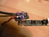
- ESS DAC is a small, easy & good sounding DAC
- I used DIP8 sockets for both plug & socket
- DIP8 socket is glued to the top of the Xilinx CPLS on the HiFace & pins point up. Thin varnish insulated wires are soldered to the 4 pins on one side of the DIP8 & ground is connected to the 4 pins of the other side. The I2S wires are soldered to the bottom of the board.
- The ESS DAC board plugs into the Hiface at right angles (it could probably be done directly on top of the HiFace).
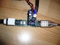
- The third pic shows the connections - LiFePO4 battery PS to the ESS DAC - you can just see the red & black wires running into the USB connector for external 5V supply - the output is through transformers to a TA2020 amplifier also running on batteries.
- My laptop is a Dell Inspiron 6000 but I have no batteries for it anymore so I'm running it from the laptop charger without the ground connected. I reckon it would sound even better running on batteries.
- ESS DAC is a small, easy & good sounding DAC
- I used DIP8 sockets for both plug & socket
- DIP8 socket is glued to the top of the Xilinx CPLS on the HiFace & pins point up. Thin varnish insulated wires are soldered to the 4 pins on one side of the DIP8 & ground is connected to the 4 pins of the other side. The I2S wires are soldered to the bottom of the board.
- The ESS DAC board plugs into the Hiface at right angles (it could probably be done directly on top of the HiFace).
- The third pic shows the connections - LiFePO4 battery PS to the ESS DAC - you can just see the red & black wires running into the USB connector for external 5V supply - the output is through transformers to a TA2020 amplifier also running on batteries.
- My laptop is a Dell Inspiron 6000 but I have no batteries for it anymore so I'm running it from the laptop charger without the ground connected. I reckon it would sound even better running on batteries.
Attachments
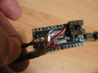
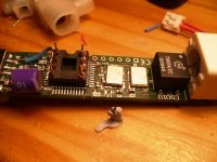
- Next pic shows the clock inductor removed from the pads marked in red & sitting on bluetak. You can see the I2S wires more clearly here going through the vias & soldered to the connection points previously shown.
- an external +3.3V (again from battery) was connected to the pad closest to C1 & battery neg connected to ground
- an external +3.3V (again from battery) was connected to the pad closest to C1 & battery neg connected to ground
Attachments
Finished most of the potential mods to this unit - here's my experience/impressions:
- The clean 3.3V supply to the clock is a must do - it clears up the sound substantially
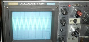
- After I did this I put a scope on the existing 3.3V on-board - pic below - looked like 40mV peaks @ 80KHz?
- I took off the 3.3V switching down-converter & supplied 3.3V from battery to the rest of the board - another jump in clarity - not surprising as this supplies the PS to the CPLD IO banks & the clock is Muxed & buffered there.
- The only switching converter left on board is 1.8V & removing it may not have too much benefit as it supplies the core logic to the CPLD (apart from removing whatever hash this puts on the ground plane which may be no bad thing)
This is the best audio I've had in my system to date - I reckon it would compete well against the best. The weakest link now, I reckon, is the fact that there's no way to galvanically isolate the USB 2.0 signal so the quality of the sound depends on the computer (& PS) feeding it.
Time to shift it to my main listening area and out of the work-room & do a bit of listening before I tackle the Musiland or maybe the Squeezebox receiver
- The clean 3.3V supply to the clock is a must do - it clears up the sound substantially
- After I did this I put a scope on the existing 3.3V on-board - pic below - looked like 40mV peaks @ 80KHz?
- I took off the 3.3V switching down-converter & supplied 3.3V from battery to the rest of the board - another jump in clarity - not surprising as this supplies the PS to the CPLD IO banks & the clock is Muxed & buffered there.
- The only switching converter left on board is 1.8V & removing it may not have too much benefit as it supplies the core logic to the CPLD (apart from removing whatever hash this puts on the ground plane which may be no bad thing)
This is the best audio I've had in my system to date - I reckon it would compete well against the best. The weakest link now, I reckon, is the fact that there's no way to galvanically isolate the USB 2.0 signal so the quality of the sound depends on the computer (& PS) feeding it.
Time to shift it to my main listening area and out of the work-room & do a bit of listening before I tackle the Musiland or maybe the Squeezebox receiver
Attachments
Finished most of the potential mods to this unit - here's my experience/impressions:
- The clean 3.3V supply to the clock is a must do - it clears up the sound substantially
- After I did this I put a scope on the existing 3.3V on-board - pic below - looked like 40mV peaks @ 80KHz?
- I took off the 3.3V switching down-converter & supplied 3.3V from battery to the rest of the board - another jump in clarity - not surprising as this supplies the PS to the CPLD IO banks & the clock is Muxed & buffered there.
- The only switching converter left on board is 1.8V & removing it may not have too much benefit as it supplies the core logic to the CPLD (apart from removing whatever hash this puts on the ground plane which may be no bad thing)
This is the best audio I've had in my system to date - I reckon it would compete well against the best. The weakest link now, I reckon, is the fact that there's no way to galvanically isolate the USB 2.0 signal so the quality of the sound depends on the computer (& PS) feeding it.
Time to shift it to my main listening area and out of the work-room & do a bit of listening before I tackle the Musiland or maybe the Squeezebox receiver
Wow, Looks interesting ! I'm wondering how does anyone else galvanically isolate the USB signal?
Wow, Looks interesting ! I'm wondering how does anyone else galvanically isolate the USB signal?
Most do not. I am tempted to try an ADuM4160. My current solution is to simply isolate the output of the dac chip through a transformer which means that all the PC ground garbage gets through to the USB chip, oversampler and dac - not ideal.
Hi Jkeny
Thanks for the great research. I've been looking for a chip to replace the 2707 and this clearly seems to work. Sadly, the implementation appears to be so poor that a complete redesign is probably required. Maybe the manufacturer would be interested in selling bare chips and drivers to diyers.
Thanks for the great research. I've been looking for a chip to replace the 2707 and this clearly seems to work. Sadly, the implementation appears to be so poor that a complete redesign is probably required. Maybe the manufacturer would be interested in selling bare chips and drivers to diyers.
Finished most of the potential mods to this unit - here's my experience/impressions:
- The clean 3.3V supply to the clock is a must do - it clears up the sound substantially
- After I did this I put a scope on the existing 3.3V on-board - pic below - looked like 40mV peaks @ 80KHz?
Maybe one could use low drop linear regulator like lm1117 instead of switching one?
Most do not. I am tempted to try an ADuM4160. My current solution is to simply isolate the output of the dac chip through a transformer which means that all the PC ground garbage gets through to the USB chip, oversampler and dac - not ideal.
No an ADUM won't work with these new USB 2.0 devices - they run at Hi-Speed (480Mbit/s) so nothing I know of is fast enough to pass this through
Don't be so harsh on the developers - I'm sure they designed the unit to be portable - mine with mods + Batteries is no longer so because it has been changed for a different goal - best sound. Still all boxed up it should be a neat unit - I never liked the idea of the unit plugging directly into the USB port anywaySadly, the implementation appears to be so poor that a complete redesign is probably required.
. It is prone to the same PS problems that arise in the Musiland also - switching regulators. But these are easily removed & when clean PS supplied instead the unit really sings so not a bad underlying design really.Don't get too hung up about the galvanic isolation - it still sounds wonderful & I don't know how much better it would be with galvanic isolation. I do know that when I power my laptop from my Linear bench supply the sound improves so maybe that is the area to focus on cleaner, non-switching power supplies to the laptop/PC? If you really want galvanic isolation then go for a Squeezebox Receiver which is what I've done. Only problem is it's limited to 16bit 44/48KHz ( 24/96 when the SB Touch is released
) but I reckon that modded this will sound wonderful also probably better than the HiFace!Hi John,
very nice job you did, congrats.
you like the sound now?
as I told you in a previous PM, I replaced onboard regulators on my hiface with ultra low noise linear regs.. tps79318 and tps79333 from TI
pinout is the same except one which I lifted and connected to a bypass cap (as per datasheet).. I also replaced two inductors following the previous reg output with two zero ohm smd jumpers. a bit tricky mod due to size.
this improved the sound quite significantly
I compared mine with stock hiface via spdif (wm8804) .. modded hiface sounds better by a margin
my mods so far : external PS, onboard regs, i2s tapping
I know you're playing with nanotech batteries for quite some time.. it's time to order some A123 lifepo4.. do you have a source in EU?
and yes, next thing I'll try is clock on battery
maybe would be a good idea to design a simple battery based PS for every critical low amperage component (DAC, hiface,..) with builtin charger/switcher
PS: USB isolation at hi speed (480Mbs) is not available on any known chip (at least to me).. maybe we can focus on I2S isolation using ADUM?
cheers,
Vale
very nice job you did, congrats.
you like the sound now
?as I told you in a previous PM, I replaced onboard regulators on my hiface with ultra low noise linear regs.. tps79318 and tps79333 from TI
pinout is the same except one which I lifted and connected to a bypass cap (as per datasheet).. I also replaced two inductors following the previous reg output with two zero ohm smd jumpers. a bit tricky mod due to size.
this improved the sound quite significantly
I compared mine with stock hiface via spdif (wm8804) .. modded hiface sounds better by a margin
my mods so far : external PS, onboard regs, i2s tapping
I know you're playing with nanotech batteries for quite some time.. it's time to order some A123 lifepo4.. do you have a source in EU?
and yes, next thing I'll try is clock on battery
maybe would be a good idea to design a simple battery based PS for every critical low amperage component (DAC, hiface,..) with builtin charger/switcher
PS: USB isolation at hi speed (480Mbs) is not available on any known chip (at least to me).. maybe we can focus on I2S isolation using ADUM
?cheers,
Vale
Last edited:
If you really want galvanic isolation then go for a Squeezebox Receiver which is what I've done. Only problem is it's limited to 16bit 44/48KHz ( 24/96 when the SB Touch is released
Will be interesting to find out how the transport function of the Hiface in comparison with the SB. By right the Hiface with propriety software should be better. But... one never know.
Ah yes, forgot, I must try one of these for the 1.8V supplyHi John,
very nice job you did, congrats.
you like the sound now
as I told you in a previous PM, I replaced onboard regulators on my hiface with ultra low noise linear regs.. tps79318 and tps79333 from TI
pinout is the same except one which I lifted and connected to a bypass cap (as per datasheet).. I also replaced two inductors following the previous reg output with two zero ohm smd jumpers. a bit tricky mod due to size.
I ordered mine from Japan (they are now manufactured in China , I believe) from an Radio Controlled aircraft shop Air Craft - Electric R/C Aircraft World Shop. They don't seem to have the 2300mAh in stock anymore. I'm not sure about sources in EU. I'll PM you!this improved the sound quite significantly
I compared mine with stock hiface via spdif (wm8804) .. modded hiface sounds better by a margin
my mods so far : external PS, onboard regs, i2s tapping
I know you're playing with nanotech batteries for quite some time.. it's time to order some A123 lifepo4.. do you have a source in EU?
Yes, well worth itand yes, next thing I'll try is clock on battery
That's exactly what I'm thinking too!maybe would be a good idea to design a simple battery based PS for every critical low amperage component (DAC, hiface,..) with builtin charger/switcher
Yes that should work, but I haven't given it much thought.PS: USB isolation at hi speed (480Mbs) is not available on any known chip (at least to me).. maybe we can focus on I2S isolation using ADUM
cheers,
Vale
Sam, I would fall in favour of the SB because it is isolated from PC by ethernet transformer & it has similar building blocks to HiFace a processor that controls Xilinx CPLD feeding I2S to DAC. I'll be removing WiFi & changing the PS, of course, with some other mods.Will be interesting to find out how the transport function of the Hiface in comparison with the SB. By right the Hiface with propriety software should be better. But... one never know.
- Status
- This old topic is closed. If you want to reopen this topic, contact a moderator using the "Report Post" button.
- Home
- Source & Line
- Digital Source
- M2TECH Hiface USB->SPDIF 24/192Khz asynch