Hi,
This is my first post on diyAudio, because I couldn't figure things out by myself.
Here's the problem:
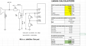
I've successfully built the LM3915 circuit as shown in the datasheet. Everything's the same except I used 10k instead of 8.06k for R2 and I've left out the 2.2 uF capacitor.
When I turn it on without an audio source, all LEDS light up, so I don't think I've made a mistake in the solder work.
When I plug in an audio source (headphone out from my stereo or computer), there are always 7 or 8 LEDs lit, regardless of the volume that is outputted by my stereo/computer. When I turn the volume up, LEDs 8,9 and sometimes 10 work as they should. So I conclude that my setup works? I just need to configure it so that it uses all the LEDs and when the volume is turned down, none of them are lit.
I'm not using a rectifier circuit, however I've built one along with a booster circuit but that didn't give a better result.
I'm thinking of building a new (better?) one from this site: http://sound.westhost.com/project60.htm
Would it help in any way?
I've tried using all kinds of different values for resistors but to no avail. I've also tried to work out the exact value I need according to Vref but I find the calculations in the datasheet somewhat confusing.
FYI: the signal on my headphone out fluctuates around 2.5V with peaks to 3V (is this correct?) and I have an adapter with adjustable voltage (3-12V) however when choosing different values, I don't really see a difference.
Hopefully someone can help me because I really want to finish this project.
Thanks in advance,
Youran
This is my first post on diyAudio, because I couldn't figure things out by myself.
Here's the problem:
I've successfully built the LM3915 circuit as shown in the datasheet. Everything's the same except I used 10k instead of 8.06k for R2 and I've left out the 2.2 uF capacitor.
When I turn it on without an audio source, all LEDS light up, so I don't think I've made a mistake in the solder work.
When I plug in an audio source (headphone out from my stereo or computer), there are always 7 or 8 LEDs lit, regardless of the volume that is outputted by my stereo/computer. When I turn the volume up, LEDs 8,9 and sometimes 10 work as they should. So I conclude that my setup works? I just need to configure it so that it uses all the LEDs and when the volume is turned down, none of them are lit.
I'm not using a rectifier circuit, however I've built one along with a booster circuit but that didn't give a better result.
I'm thinking of building a new (better?) one from this site: http://sound.westhost.com/project60.htm
Would it help in any way?
I've tried using all kinds of different values for resistors but to no avail. I've also tried to work out the exact value I need according to Vref but I find the calculations in the datasheet somewhat confusing.
FYI: the signal on my headphone out fluctuates around 2.5V with peaks to 3V (is this correct?) and I have an adapter with adjustable voltage (3-12V) however when choosing different values, I don't really see a difference.
Hopefully someone can help me because I really want to finish this project.
Thanks in advance,
Youran
IIRC the LM3915 is not actually a VU meter, just a log scale bargraph driver. You need the LM3916 to build a "proper" VU meter for audio.
/U.
Thanks for the response, but that's not really an issue. I'm trying to make an ambient LED bar that lights up according to the beat of the music, so accuracy is no big deal.
Here's one at Instructables... it probably works:
http://www.instructables.com/id/LM3915LM3916-VU-Meter/
Maybe something is unstable... try adding the suggested cap. And try a resistor between the input pin and ground, like 47k or so, and then feed the signal in through a capacitor of 0.1 to 1 uF.
http://www.instructables.com/id/LM3915LM3916-VU-Meter/
Maybe something is unstable... try adding the suggested cap. And try a resistor between the input pin and ground, like 47k or so, and then feed the signal in through a capacitor of 0.1 to 1 uF.
Hi,
I am trying to set up the esp lm3915 as a power indicator for my amp. amp is about 60W 8ohm.
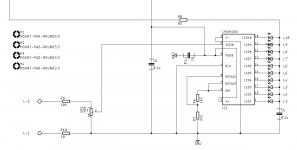
I am trying to understand the calculation for input dropping resistor to be used (R9 and VR1 setting in attached schematic).
The R6 /R7 as per the sch give a full scale sensitivity of ~ 4V for the LM3915 .
I would like to find out what values of R9 and VR1 to be used so that pin 5 sees 4V.
can someone help?
regards
Prasi
I am trying to set up the esp lm3915 as a power indicator for my amp. amp is about 60W 8ohm.
I am trying to understand the calculation for input dropping resistor to be used (R9 and VR1 setting in attached schematic).
The R6 /R7 as per the sch give a full scale sensitivity of ~ 4V for the LM3915 .
I would like to find out what values of R9 and VR1 to be used so that pin 5 sees 4V.
can someone help?
regards
Prasi
Attachments
If Your trimmer is at max position and You can't adjust input, lower R9, but be careful since pin 5 is current limited to 3mA. For 25V (78W@8) this would be 8.3K. I think the pot value is too high also. Use say 10K. This way you will have more precision adjusting and 10K also doesn't load the amp.
Or... apply an AC signal similar to Your amp's max output and then adjust values until You get 5V on pin 5.
Or... apply an AC signal similar to Your amp's max output and then adjust values until You get 5V on pin 5.
Last edited:
- Status
- This old topic is closed. If you want to reopen this topic, contact a moderator using the "Report Post" button.
- Home
- Source & Line
- Digital Source
- Help with LM3915 LED VU meter