Fred,
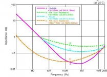
The upper one IS comparing different cap types NOT oscon only. To be specific oscon 47uF 16v, Al-E 47uF 16v, Ta 47uF 16v and Al-E 1000uF 16v
The lower one IS oscon only but different values.
It probably don't show good enough on the heavily compressed jpeg...her is the original pdfOscon pdf
The upper one IS comparing different cap types NOT oscon only. To be specific oscon 47uF 16v, Al-E 47uF 16v, Ta 47uF 16v and Al-E 1000uF 16v
The lower one IS oscon only but different values.
It probably don't show good enough on the heavily compressed jpeg...her is the original pdfOscon pdf
once again........
The top graph Fig. 5-1 shows IMPEDANCE verses frequency. Your comment was one on non linearity of ESR, which is show on the bottom graph 5-2 and is for the OSCON CAPS ONLY. ABCD traces are even for different value and voltage caps for the two graphs.
From the OSCON pdf:
"Fig.5-2 shows the impedance and ESR frequency characteristics for each size of OSCON."
You seem to have misunderstood my post as well as the graph. Please look at the links to understand the difference between capacitor impedance and ESR. You can tell nothing about the ESR from the top graph.
Attachments
Some can't see the forrest...only trees
 , -you are right, however they are related, particularly during lower frequencies so I still say the upper graph has merit as reference to my original post.
Irrespective Fred's urge to get all the details correct my initial post still offers a likely explanation to the findings regarding oscon expressed in this post i.e. the oscon will typically have lower esr in the area 5 kHz to 100kHz and similar to the elco under 5 kHz so you end up with less linear esr compared to the elco.
, -you are right, however they are related, particularly during lower frequencies so I still say the upper graph has merit as reference to my original post.Irrespective Fred's urge to get all the details correct my initial post still offers a likely explanation to the findings regarding oscon expressed in this post i.e. the oscon will typically have lower esr in the area 5 kHz to 100kHz and similar to the elco under 5 kHz so you end up with less linear esr compared to the elco.
Out of your tree
The graph doesn't show the curves for B and C below the frequency below where the they intersect curve A. The capacitance of an ideal 47uf cap at 5 kHz is about 1.47 ohms. The graph is logarithmic for the frequency and impedance scales. An ideal cap would appear as a straight line on this curve as capacitance verses frequency is a linear relationship. At 5 kHz the capacitive component of the impedance is about two orders of magnitude above the ESR component. the curve converges to the linear curve well above 10 kHz.
There is neither the data or resolution to compare the ESR linearity of this caps from this graph.
It is interesting some of the most highly regarded electrolytic caps for audio have low resistance electrolytes i.e. Black Gates, Oscon, Rifa PHE any a few others I have played with. Anecdotal opinions of the relative merits of capacitor types will have to include some information on the circuit in which they were used , before I would jump to the conclusions about the technical reasons for their differences. Bypassing very low ESR caps can be a sonic disaster as well the use of very low ESR caps with some voltage regulator circuits, like the Later Jung op amp based circuits.* Low ESR seems to be an important factor in even film and conventional dielectric. The Panasonic HF, HFQ, and FC come to mind as very good caps with low ESR compared to other conventional electrolytics.
More on ESR:
http://www.quadtechinc.com/resources/library/app_notes/035002.pdf
http://www.quadtechinc.com/newsletter/esr.pdf
Capacitor bypassing:
http://www.ultracad.com/esrbcap.pdf
I will leave the expertise in forestry to you, but on this topic I know more than enough to see when someone is out on a limb.
Sorry to got OT for a sec...
Fred, you're posts are as ever incredibly useful sources of data for those who chose to read them, but I have to relate some experience with regard to the statement above.
Oscons (of the SG, or SP series only*) are the capacitor of choice within the later Jung reg's, a view strongly supported by Walt himself and subsequently by myself, based on actual listening tests.
An Oscon at the regulator output (with the AD825-based units) works admirably and with no stability-related issues. The Q of the cap being nowhere near as bad as a film alternative, a definitve recipe for phase shifts and oscillation!
There are issues with ESR in conjunction with the tracking pre-reg, but even then degrading the ESR with some additional milliohm level of series resistance brings sonic benefits, compared to many of the alternative, higher ESR capacitors one could use.
By no means a comprehensive assessment, but one that has yet to be proved wrong by my ears.
Andy.
*This choice is a sonic one, not an ESR / data related one - I'm always open to other suggestions though")
...as well the use of very low ESR caps with some voltage regulator circuits, like the Later Jung op amp based circuits
Fred, you're posts are as ever incredibly useful sources of data for those who chose to read them, but I have to relate some experience with regard to the statement above.
Oscons (of the SG, or SP series only*) are the capacitor of choice within the later Jung reg's, a view strongly supported by Walt himself and subsequently by myself, based on actual listening tests.
An Oscon at the regulator output (with the AD825-based units) works admirably and with no stability-related issues. The Q of the cap being nowhere near as bad as a film alternative, a definitve recipe for phase shifts and oscillation!
There are issues with ESR in conjunction with the tracking pre-reg, but even then degrading the ESR with some additional milliohm level of series resistance brings sonic benefits, compared to many of the alternative, higher ESR capacitors one could use.
By no means a comprehensive assessment, but one that has yet to be proved wrong by my ears.
Andy.
*This choice is a sonic one, not an ESR / data related one - I'm always open to other suggestions though
oscon lead oxidation
this might be off topic but still regarding the use of os-cons,
does anybody experience some sort of "oxidation" on their oscon's lead, especially after quite some months in operation?
in my experience the oxidation is very similar to silver oxidation.
this happens to the SH series (long life) also to older ones without series marking (blue-ish purple jacket)
could it be caused by the organic semiconductor residue/leaks ?
or maybe it uses silver/silver plated lead ?
maybe "audio series" with gold plating do not suffer from the same problem.
I was just hoping that the oxidation do not cause any problem whatsoever, anyone ?
Jung regulators
Some of the earlier versions with other op amps and using remote sensing ( AD797 I believe) did not tolerate high Q low ESR electrolytics or film bypass caps. I have the Oscons on a opamp base regulator that I built as well.
http://www.e-insite.net/ednmag/archives/1997/010297/01di_03.htm
Jung, Walt, "Regulators for high-performance audio, Parts 1 and 2," The Audio Amateur, Issues 1 and 2, 1995.
Attachments
Fred,
Yes, the AD797 definitely had narrower stability margins.
Didn't sound as good either
Your original point stands though, ESR can be a killer to stability in a standard reg.
For those that want a good 5V supply, look at some of the fast transient performance reg's designed for PC motherboards etc. These are designed to be stable, and have better transient specs, with very low ESR caps (+ve supplies only though).
Andy.
????
Fred,
I am not sure this debate helps anyone and I admit to having a problem understanding what you're trying to get at. You seem to be more focused on the references in my suggestion then the suggestion itself.
I admit I am just a happy hobbyist that typically just build and listen...until I am satisfied.
Having played with oscons for many years I think I know how to make the most of them.
Assuming my being out on a limp....why don't you offer your own expert opinion on why our fellow diy have the experience they have regarding oscons.
BTW...
Great, are you saying that sanyo got it all wrong and faked the graphs shown earlier or what?
Fred,
I am not sure this debate helps anyone and I admit to having a problem understanding what you're trying to get at. You seem to be more focused on the references in my suggestion then the suggestion itself.
I admit I am just a happy hobbyist that typically just build and listen...until I am satisfied.
Having played with oscons for many years I think I know how to make the most of them.
Assuming my being out on a limp....why don't you offer your own expert opinion on why our fellow diy have the experience they have regarding oscons.
BTW...
eh? does it not, who says. I read it align with the other caps. Why would they exclude all caps but the low impedance 1000uF Al. If you live as you learn you'll also see the graphs also intersect in higher frequencies.The graph doesn't show the curves for B and C below the frequency below where the they intersect curve A.
The capacitance of an ideal 47uf cap at 5 kHz is about 1.47 ohms. The graph is logarithmic for the frequency and impedance scales. An ideal cap would appear as a straight line on this curve as capacitance verses frequency is a linear relationship. At 5 kHz the capacitive component of the impedance is about two orders of magnitude above the ESR component. the curve converges to the linear curve well above 10 kHz.
Great, are you saying that sanyo got it all wrong and faked the graphs shown earlier or what?
I guess it would be "or what?"
All I was saying is that you can't get data about the ESR from the top graph. If you are going to try and figure out the measured parameters corelation to the sound you have to know what measurements you are looking at.
I have used the Oscons as well and even talked to the technical sales group in my last telecom job. Why someone had a particular experience with a certain type of cap would depend on the circuit in which it was used. The Black Gate and Oscon both use carbon loaded electrolyte paper and have very simular measurements. I have meaured both on an HP impedance meter. One mistake many people make is bypassing very low ESR caps with a film cap, which can be a sonic disaster in some cases. I don't know all the reasons caps sound different and sure wouldn't try to figure it all out looking at a graph. No one faked any graphs but you need to know what data is there and how to interprete it.
There have been many disscussions on microphonics of capacitors, breakin, bypassing, and their interaction with low impedance regulators when used on the output on the forum. I don't know why you are focusing on a few post where some said they don't like the Oscons, I have heard the same observation about the Black Gates which I like even better than the Oscons.
I have given several references on capacitor measurements and explained very clearly the data on the Oscon graphs. I am not the one who decided what a cap sounded like from data on a graph, and not even the right data at that. If you can't understand the difference between ESR and impedance after I have bent over backwards to explain it and provided links on the subject, I don't know what to do....... The knowledge would come in real handy the next time you try to read a capacitor graph though.
You can lead a horse to water but you can't make him think. You're welcome for the gratitude you have shown for all my efforts to explain this subject. When lecturing on a subject it helps to know more than your audience. Try it sometime.........
Re: Jung regulators
Fred,
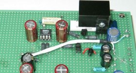
I see you like ohmite metal devil...so do I!
Don't tell me you just had them in your junk box
What's that funny looking star on the bottom right of the board?
The GND? Does it really work better with all those tiny wires, really?
Fred Dieckmann said:Some of the earlier versions with other op amps and using remote sensing ( AD797 I believe) did not tolerate high Q low ESR electrolytics or film bypass caps. I have the Oscons on a opamp base regulator that I built as well.
http://www.e-insite.net/ednmag/archives/1997/010297/01di_03.htm
Jung, Walt, "Regulators for high-performance audio, Parts 1 and 2," The Audio Amateur, Issues 1 and 2, 1995.
Fred,
I see you like ohmite metal devil...so do I!
Don't tell me you just had them in your junk box
What's that funny looking star on the bottom right of the board?
The GND? Does it really work better with all those tiny wires, really?
You can lead a horse to water but you can't make him think. You're welcome for the gratitude you have shown for all my efforts to explain this subject.
I guess I am one that like to simplify things and only read the short answers...Sorry.
When lecturing on a subject it helps to know more than your audience. Try it sometime.........
I figured this was where I went wrong.....my post was really to offer my practical experiance of oscons...they can be used succesfully for analog as well.
btw I do but as you clearly figured not on the topic of caps or any other technical topic for that matter.......
Ignorance is bliss....
The omite devil made me do it!
"Fred,
I see you like ohmite metal devil...so do I! Don't tell me you just had them in your junk box"
No and not on the board either...... Those are Corning RN60Ds on the board. A favorite of Conrad Johnston on most of there stuff in the past. The spider looking wire is a single point ground scheme.
For real single point grounding, having a seperate return to a single node is the important thing rather than just low impedance traces that still might carry several ground return currents through a common impedance.
"Ignorance is bliss...."
But the Truth will set you free!
I too continue to look for measurable data that correlates with sound quality. A hopeless task in some cases, but it never hurts to wonder.
Coupling capacitors for digital audio
I am currently working on a zero-oversampling DAC.
By reading this thread I have gathered that for decoupling purposes ceramic is best for digital (probably COG is best). The high lead inductance accompanying film and foil capacitors makes these poor with the very high frequencies involved. The noise associated with ceramics is less of a problem when used for decouping.
Is my understanding essentially correct?
What I really wish to know is "What is best type of capacitor for coupling digital signals?" I am working with frequencies ranging from 44 Khz to 100Mhz in some parts of my circuit!
Some people say 'silver mica' is best- but these capacitors become quite bulky. Is there an alternative? Will ceramics or polypropylenes do?
Archived "Dead"Link
I found, like others may have, that the link given no longer works;
Therefore, I have attached an archive link for those who wish to read the info:
http://web.archive.org/web/20001010163059/http://www.ultracad.com/esrbcap.pdf
More on capacitor bypassing:
http://www.ultracad.com/esrbcap.pdf
I found, like others may have, that the link given no longer works;
Therefore, I have attached an archive link for those who wish to read the info:
http://web.archive.org/web/20001010163059/http://www.ultracad.com/esrbcap.pdf
- Status
- This old topic is closed. If you want to reopen this topic, contact a moderator using the "Report Post" button.
- Home
- Source & Line
- Digital Source
- Use OS-CON in Vcc?