Hello everybody,
I am planning to modify my CD-Player. There are some electrolyte capacities around DAC chip, Burr-Brown PCM1716, for bypass or decouple. I want to upgrade them but I have doubt that can I use OS-CON as bypass caps to the power supply of Vcc of the DAC chip?
I think OS-CON are good things in digital circiut but use in Vcc also good?
The way I read the original post there are a couple of questions:
1. Can I use OsCon's? Yes
2. Should I use OsCon's? Well that depends. OsCon's are high quality units with several advantages such as low impedance, extremely long life etc. Disadvantages include cost, and other types reportedly are even higher performing.
3. There are analog and digital power pins in the DAC chip. The analog power pins are of course the most sensitive, but use high quality parts and techniques for both.
4. If you do decide to replace the electrolytics which is probably a very good idea, consider adding a film or ceramic (depending on where you are) bypass. There has been several threads on the benefits of different types of bypassing which you should easily find if you search the forum.
Petter
Petter said:The way I read the original post there are a couple of questions:
1. Can I use OsCon's? Yes
2. Should I use OsCon's? Well that depends. OsCon's are high quality units with several advantages such as low impedance, extremely long life etc. Disadvantages include cost, and other types reportedly are even higher performing.
3. There are analog and digital power pins in the DAC chip. The analog power pins are of course the most sensitive, but use high quality parts and techniques for both.
4. If you do decide to replace the electrolytics which is probably a very good idea, consider adding a film or ceramic (depending on where you are) bypass. There has been several threads on the benefits of different types of bypassing which you should easily find if you search the forum.
Petter
Hi Petter,
Someone tell me that the high quality electrolytic capacities need no to add small cap bypass but I am confused.
Should I add film or ceramic caps to bypass for BG N TYPE?
That depends on the demands of the circuit being powered. For digital circuitry with fast rise times, it is almost certain that you need low-inductance capacitors on the Vcc line near the package. Usually you need two ceramic capacitors of decreasing value, as well as the bulk capacitor.
For fast analog circuits, you probably need a single ceramic capacitor near the package, such as .1µF, in addition to the bulk capacitor.
For audio frequency analog circuitry, a bulk capacitor (electrolytic, OS-CON, ...) on the Vcc is plenty.
For fast analog circuits, you probably need a single ceramic capacitor near the package, such as .1µF, in addition to the bulk capacitor.
For audio frequency analog circuitry, a bulk capacitor (electrolytic, OS-CON, ...) on the Vcc is plenty.
caution
"Should I add film or ceramic caps to bypass for BG N TYPE?"
Black gate caps usually sound bad with bypass caps. Try about 47uf to 200uF as close to the chip as you can get it with low inductance traces. The standard type work fine for this and more black gates for a given budget would be a better bet. Try them close to the input terminals on you regulators. I have paralleled similar value Black gates with good results before.
What many people seem to consider the standard for decoupling these days is:
Digital circuits: Ceramic capacitors
Analog circuits: Film capacitors
Whether they are needed or not is another matter. It is still good practice to use decoupling capacitors in addition to the bulk capacitances you have already identified. I always use additional decoupling.
The reason for using small caps in parallel with larger ones is that smaller units typically have far lower inductance than larger ones. The problem with bypass capacitors (if you are unlucky) is that the wrong combination can lead to resonant effects. This is typically more of a problem in digital circuits than analog circuits, though. If in doubt bypass the analog section with .1uF or 1/10th the value of the other cap using film, and the digital section with 1/10th to 1/100th the value of the unit being bypassed.
Don't worry too much. It is very unlikely that the addition of bypass and improved quality of caps will have any negative influence whatsoever on the sound.
To give some pushback, I personally like OsCon's")
Your mileage may vary.
Petter
Digital circuits: Ceramic capacitors
Analog circuits: Film capacitors
Whether they are needed or not is another matter. It is still good practice to use decoupling capacitors in addition to the bulk capacitances you have already identified. I always use additional decoupling.
The reason for using small caps in parallel with larger ones is that smaller units typically have far lower inductance than larger ones. The problem with bypass capacitors (if you are unlucky) is that the wrong combination can lead to resonant effects. This is typically more of a problem in digital circuits than analog circuits, though. If in doubt bypass the analog section with .1uF or 1/10th the value of the other cap using film, and the digital section with 1/10th to 1/100th the value of the unit being bypassed.
Don't worry too much. It is very unlikely that the addition of bypass and improved quality of caps will have any negative influence whatsoever on the sound.
To give some pushback, I personally like OsCon's
Your mileage may vary.
Petter
some advice ........
"Don't worry too much. It is very unlikely that the addition of bypass and improved quality of caps will have any negative influence whatsoever on the sound. "
It is not hard to real screw up the sound with the wrong type and value of bypass cap. The low ESR of some of the conductive electrolyte can make for a very high Q resonance. I had to try dozens of combinations of polypropylene caps and low ESR electrolytic caps of the to get the sound right for a video amp passing an SPDIF digital signal. A 680 uF cap sounded a lot better than 1000 uF or 470 uF. The form factor electrolytic made a big difference. Same value, voltage, manufacturer, and type cap, the skinnier taller cap sounded much better. The bandwidth of this video amp wasn't as fast as some of op amps people are using for analog stages now. Digital circuits are sensitive to bypassing also. It pays to experiment with this stuff. I would worry about it, but then I have a lot of experience with this. I never cease to be amazed by some of the "advice" I read here. Oh well ..........
Re: some advice ........
Fred,
Some people want simple solutions and simple advice. They are not eager to try dozens of combinations to really know what works best. Sometimes I feel the same So what can you advice to them? A fool proof combination that works in most cases?
I read the articles by Pete Goudreau and the threads about famous triplets, but even after that I'm still not always quite sure what caps to choose. Are you?
Fred Dieckmann said:I never cease to be amazed by some of the "advice" I read here. Oh well ..........
Fred,
Some people want simple solutions and simple advice. They are not eager to try dozens of combinations to really know what works best. Sometimes I feel the same
So what can you advice to them? A fool proof combination that works in most cases?I read the articles by Pete Goudreau and the threads about famous triplets, but even after that I'm still not always quite sure what caps to choose. Are you?
Koinichiwa,
Before I come to the Os-Con topic first some general remarks on the subject of BG's. Many people like BG's, some others dislike them. I fall into the latter category. I think it is worth noting a few facts.
First, most generic BG's (excepting N, NX and NX-HiQ) have more Distortion than Sanyo Os Con. There used to be more measurements posted (larger values, larger selection of Electrolytic Brands and Values showing audio grade Elna's and Os-Con notably superior to other BG series) on the site linked below, sadly they seem gone.
Distortion in Capacitors from JP
Secondly, I find most Film Capacitors most of the time better than ANY electrolytic, including BG's. In fact, the "BG Sound" is to my ears typhically "High End", meaning a sound where detail is trust, almost brutally forced at you, to the detriment of musical enjoyment. I find I almost always have to remove them from gear I use after trying them, as the systems overall sound becomes unpleasant to my ears.
Thirdly, few "Audiophile" Parts sellers sell anything but BG's. When I asked one company why they did not sell any number of superior industrial products they told me: "They may be better but there is less audible diffierence and anyway, our margins on those things are too low to sell them."
Now to the PCM1716 (and similar) and what to do (apart from ripping out and replacing with TDA1543).
For the digital decoupling I recommend a combo of SMD Ceramic Capacitors (I still use a "triplet" system inspired by Pete Gourdeu, but more recent tests by other published here have shown better options).
Add to that a good quality "bulk" Capacitor, currently good choices are Rubycon ZA Series and the various manufacturers (it used to be only Sanyo, others have followed) Organic Semiconductor (Os-Con) Capacitors. I find the SH Series from Sanyo notably better than the others.
Digital supply (Digital filter etc) BTW is pin 8.
The DAC's themself are Pin 9 and 20 and should be separatly decoupled, to the same standard as the Digital supply, the DAC's are jolly noisy too.
The next step is the supply for the analogue outputstage/filter Op-Amp's (Pin 15) where I feel an Elna Silmic or Cerafine capacitor is the better choice, as large a value as physically fits and with film bypass capacitors (always bypass two times, not just one cap.
Two VERY often overlooked capacitors are on the Pin's 11 and 18. They are DC blockers for the internal Op-Amp's feedback loop. They are as critical or more so than the other Cap's around the PCm1716, I'd again recommend Elna Silmic or Cerfine as large value as will fit (6.3V will do fine) or if you have the space suitable value Film Capacitors, the same goes for the Output Coupling Capacitors.
Now the bad news. Even at it's best (improved Powersupplies, optimised decoupling etc.) the PCM1716 is still pretty bad. I'd not say it totally sucks (as it does with generic cap's around it), but it's still plenty bad. I would personally recommend against investing any money and time into anything with chips from that specific Burr Brown Series (PCM1716, 1728, 1732 et al), they are very much one wash.
I have come across worse, but that tended ultra-cheap single chip (everything from servo, decoder, digital filter and DAC on one big chip, noisy as hell, awful) CD-Players from the major boxshifter makers, where literally everything is lost.
Sayonara
Marlowe said:
I am planning to modify my CD-Player. There are some electrolyte capacities around DAC chip, Burr-Brown PCM1716, for bypass or decouple. I want to upgrade them but I have doubt that can I use OS-CON as bypass caps to the power supply of Vcc of the DAC chip?
I think OS-CON are good things in digital circiut but use in Vcc also good?
Before I come to the Os-Con topic first some general remarks on the subject of BG's. Many people like BG's, some others dislike them. I fall into the latter category. I think it is worth noting a few facts.
First, most generic BG's (excepting N, NX and NX-HiQ) have more Distortion than Sanyo Os Con. There used to be more measurements posted (larger values, larger selection of Electrolytic Brands and Values showing audio grade Elna's and Os-Con notably superior to other BG series) on the site linked below, sadly they seem gone.
Distortion in Capacitors from JP
Secondly, I find most Film Capacitors most of the time better than ANY electrolytic, including BG's. In fact, the "BG Sound" is to my ears typhically "High End", meaning a sound where detail is trust, almost brutally forced at you, to the detriment of musical enjoyment. I find I almost always have to remove them from gear I use after trying them, as the systems overall sound becomes unpleasant to my ears.
Thirdly, few "Audiophile" Parts sellers sell anything but BG's. When I asked one company why they did not sell any number of superior industrial products they told me: "They may be better but there is less audible diffierence and anyway, our margins on those things are too low to sell them."
Now to the PCM1716 (and similar) and what to do (apart from ripping out and replacing with TDA1543).
For the digital decoupling I recommend a combo of SMD Ceramic Capacitors (I still use a "triplet" system inspired by Pete Gourdeu, but more recent tests by other published here have shown better options).
Add to that a good quality "bulk" Capacitor, currently good choices are Rubycon ZA Series and the various manufacturers (it used to be only Sanyo, others have followed) Organic Semiconductor (Os-Con) Capacitors. I find the SH Series from Sanyo notably better than the others.
Digital supply (Digital filter etc) BTW is pin 8.
The DAC's themself are Pin 9 and 20 and should be separatly decoupled, to the same standard as the Digital supply, the DAC's are jolly noisy too.
The next step is the supply for the analogue outputstage/filter Op-Amp's (Pin 15) where I feel an Elna Silmic or Cerafine capacitor is the better choice, as large a value as physically fits and with film bypass capacitors (always bypass two times, not just one cap.
Two VERY often overlooked capacitors are on the Pin's 11 and 18. They are DC blockers for the internal Op-Amp's feedback loop. They are as critical or more so than the other Cap's around the PCm1716, I'd again recommend Elna Silmic or Cerfine as large value as will fit (6.3V will do fine) or if you have the space suitable value Film Capacitors, the same goes for the Output Coupling Capacitors.
Now the bad news. Even at it's best (improved Powersupplies, optimised decoupling etc.) the PCM1716 is still pretty bad. I'd not say it totally sucks (as it does with generic cap's around it), but it's still plenty bad. I would personally recommend against investing any money and time into anything with chips from that specific Burr Brown Series (PCM1716, 1728, 1732 et al), they are very much one wash.
I have come across worse, but that tended ultra-cheap single chip (everything from servo, decoder, digital filter and DAC on one big chip, noisy as hell, awful) CD-Players from the major boxshifter makers, where literally everything is lost.
Sayonara
Merhaba,
Just as a sidenote: I remarked that technically superior components not always guarantee good sonic results. Or am I kicking in an open door now as a dutch saying goes ?!?!
For instance OSCON as decoupling cap for opamps ruins sound ( and yes I gave them time ). Tried this several times in various devices before I decided to use them only in digital electronics where they excel. Unfortunately I don't know the series I am using because it is not printed on the caps. I am not complaining as I should be glad I could find them. Availability is an issue just as with Silmic. Did you experience the same, Kuei, because you advise to use Cerafine/Silmic in the analog part ???
But technically "inferior" MKT caps ( Siemens, 5 mm pitch ) which had a suspicion on them perform remarkably well as coupling cap in places where an electrolytic was, even better than "superior" film caps
Film caps often have too long wires to use them in digital electronics where RF is an issue. My search for good caps in digital ended with BG NX HiQ and OSCON. Using them instead of the normal crap is an improvement but the last drops of performance can be sqeeuzed out when one is prepared to do research with the triplet-like paralleling. Considering the enormous amount of time it takes and the fragility of todays environmentally OKed PCB material I skip that one with the newer devices. I bypass OSCON with a SMD ceramic cap but with NX HiQ I learnt the hard way that they don't like this at all.
Kuei, did you see the discussion in another thread about this ?
http://www.diyaudio.com/forums/showthread.php?s=&threadid=14781&pagenumber=2
Hosca kalin
Just as a sidenote: I remarked that technically superior components not always guarantee good sonic results. Or am I kicking in an open door now as a dutch saying goes ?!?!
For instance OSCON as decoupling cap for opamps ruins sound ( and yes I gave them time ). Tried this several times in various devices before I decided to use them only in digital electronics where they excel. Unfortunately I don't know the series I am using because it is not printed on the caps. I am not complaining as I should be glad I could find them. Availability is an issue just as with Silmic. Did you experience the same, Kuei, because you advise to use Cerafine/Silmic in the analog part ???
But technically "inferior" MKT caps ( Siemens, 5 mm pitch ) which had a suspicion on them perform remarkably well as coupling cap in places where an electrolytic was, even better than "superior" film caps
Film caps often have too long wires to use them in digital electronics where RF is an issue. My search for good caps in digital ended with BG NX HiQ and OSCON. Using them instead of the normal crap is an improvement but the last drops of performance can be sqeeuzed out when one is prepared to do research with the triplet-like paralleling. Considering the enormous amount of time it takes and the fragility of todays environmentally OKed PCB material I skip that one with the newer devices. I bypass OSCON with a SMD ceramic cap but with NX HiQ I learnt the hard way that they don't like this at all.
an Elna Silmic or Cerafine capacitor is the better choice, as large a value as physically fits and with film bypass capacitors (always bypass two times, not just one cap.
Kuei, did you see the discussion in another thread about this ?
http://www.diyaudio.com/forums/showthread.php?s=&threadid=14781&pagenumber=2
Hosca kalin
why don't you guys take a look here?
http://diyparadise.com/cap/dare_to_compare.html
i find oscons great for digital but not so for analog applications. have modified a few dacs just be taking out whatever electrolytics they have and replacing them with oscons. err, not all the caps, just the one near the clock, digital receiver and digital supply side of the dac.
so far so good. sounds better. works great!
DonJuan
Koinichiwa,
If you mean the naked, stacked film ones - they are some of my favourites, phantastically low inductance.
Didn't see it then. If you make sure to have Capacitors with broadly matched ESR AND arrange the layout correctly (lowest Value/inductance cap comes closest to the point you measure, largervalue/inductance ones with longer loops) you will find everything to be a major improvement using multiple cap's.
If you "bypass" the way many people do (where the theoretically lower inductance "bypass" has long leads and hence high inductance) you are asking for trouble of course.
I know some people who insisted bypassing "does not work", untill I illustrated to them that it does and very well too and that they had only been doing it wrong....
Sayonara
jean-paul said:But technically "inferior" MKT caps ( Siemens, 5 mm pitch ) which had a suspicion on them perform remarkably well as coupling cap in places where an electrolytic was, even better than "superior" film caps
If you mean the naked, stacked film ones - they are some of my favourites, phantastically low inductance.
jean-paul said:Kuei, did you see the discussion in another thread about this ?
http://www.diyaudio.com/forums/showthread.php?s=&threadid=14781&pagenumber=2
[/B]
Didn't see it then. If you make sure to have Capacitors with broadly matched ESR AND arrange the layout correctly (lowest Value/inductance cap comes closest to the point you measure, largervalue/inductance ones with longer loops) you will find everything to be a major improvement using multiple cap's.
If you "bypass" the way many people do (where the theoretically lower inductance "bypass" has long leads and hence high inductance) you are asking for trouble of course.
I know some people who insisted bypassing "does not work", untill I illustrated to them that it does and very well too and that they had only been doing it wrong....
Sayonara
The stacked ones were good, I recall two versions. One with silver sleeve colour and one with green sleeve. IIRC the green was MKC. They suffered quickly from damage when heated too much. You could easily change capacitance by cutting off a thin sheet. They are obsolete for a long time now ( 10 years ? ).
I was referring to these Siemens/Epcos stacked caps, they are available in 2.2 uF and 3.3 uF at 5 mm pitch which makes them suitable as replacement for electrolytics in some ( but not all ) cases. Datasheets can be found here: http://www.epcos.com/inf/20/20/db/fc_01/00150040.pdf
I was referring to these Siemens/Epcos stacked caps, they are available in 2.2 uF and 3.3 uF at 5 mm pitch which makes them suitable as replacement for electrolytics in some ( but not all ) cases. Datasheets can be found here: http://www.epcos.com/inf/20/20/db/fc_01/00150040.pdf
Attachments
Koinichiwa,
I believe you are correct. The green ones where my favuourites when modding SS Gear. Wherever I was uncofortable replacing an 'elcap that blocked no DC (normally) I'd drop one of these chipcaps in instead, cheap, good, effective.
I still get the naked MKT versions from my local distributor though, Epcos datasheet below:
http://www.epcos.com/inf/20/20/db/fc_01/00410056.pdf
They look real nice too.
BTW, do you know anyone in Europe who sells without too much hassle for the customer the Rubycon SWR Series Mylars in quanteties less than 1,000pcs? These go up to 100uF/35V in small form factor. Lovely stuff, except you need to fly JP to get them... ;-)
http://www.rubycon.co.jp/english/new/ctlg/e_pdfs/film/e_SWR.pdf
Sayonara
jean-paul said:The stacked ones were good, I recall two versions. One with silver sleeve colour and one with green sleeve. IIRC the green was MKC.
I believe you are correct. The green ones where my favuourites when modding SS Gear. Wherever I was uncofortable replacing an 'elcap that blocked no DC (normally) I'd drop one of these chipcaps in instead, cheap, good, effective.
I still get the naked MKT versions from my local distributor though, Epcos datasheet below:
http://www.epcos.com/inf/20/20/db/fc_01/00410056.pdf
jean-paul said:I was referring to these Siemens/Epcos stacked caps, they are available in 2.2 uF and 3.3 uF at 5 mm pitch which makes them suitable as replacement for electrolytics in some ( but not all ) cases. Datasheets can be found here: http://www.epcos.com/inf/20/20/db/fc_01/00150040.pdf
They look real nice too.
BTW, do you know anyone in Europe who sells without too much hassle for the customer the Rubycon SWR Series Mylars in quanteties less than 1,000pcs? These go up to 100uF/35V in small form factor. Lovely stuff, except you need to fly JP to get them... ;-)
http://www.rubycon.co.jp/english/new/ctlg/e_pdfs/film/e_SWR.pdf
Sayonara
Obvious question but did you try :
RUBYCON CORPORATION U.K. BRANCH
Aqua House, The Runway, South Ruislip, Middlesex, HA4 6SE, UNITED KINGDOM
Tel : 44-020-8842-3221 Fax : 44-020-8841-7691 ??
Anyway, I'll ask my distributor about them. They look promising with respect to case size but the datasheet is scarce in information.
RUBYCON CORPORATION U.K. BRANCH
Aqua House, The Runway, South Ruislip, Middlesex, HA4 6SE, UNITED KINGDOM
Tel : 44-020-8842-3221 Fax : 44-020-8841-7691 ??
Anyway, I'll ask my distributor about them. They look promising with respect to case size but the datasheet is scarce in information.
I guess I am the odd one out but find oscon good for analogue as well.
It will typically not be an sonic improvement if you just replace the average elco with the same or lower value oscon.
Oscon's esr can very well be LESS linear over the analogue frequency ranges then a low imp, higher value elco...hence your experience.
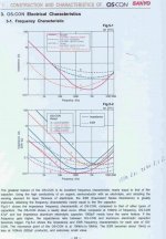
To use their strengths you have to consider how each caps esr vary over frequency and mach it to the needs of your application so that it is linear.
Study the pic and you'll see what I am trying to say.
It will typically not be an sonic improvement if you just replace the average elco with the same or lower value oscon.
Oscon's esr can very well be LESS linear over the analogue frequency ranges then a low imp, higher value elco...hence your experience.
To use their strengths you have to consider how each caps esr vary over frequency and mach it to the needs of your application so that it is linear.
Study the pic and you'll see what I am trying to say.
Attachments
Intro to graph reading 101
I would look at the graphs a little closer. The top one is a graph of
impedance verses frequency. That is the series combination of capacitance, winding and lead inductance, and ESR (equivalent series RESISTANCE) Greater ESR makes shallower curves. You can model this in spice with ideal components and you will get very close curves. The bottom graph is the change in ESR with frequency, the nonlinearity of the resistive component of the impedance as a function of frequency. This ESR vs. frequency data is given for only the Oscon caps so I know how you are comparing something that is not shown on the graph.
By the way..... you can tell what a cap sounds like from a graph, even if you know how to read it. Read the label on the y axis of the graphs if you think I am confused. I might try and find some data on the ESR vs. Frequency for a conventional electrolytic cap later.
For more in depth information on caps:
http://www.chemi-con.com/u7002/characteristics.php
http://hyperphysics.phy-astr.gsu.edu/hbase/electric/impcom.html#c1
It's a full time job straightening you guys out.................
- Status
- This old topic is closed. If you want to reopen this topic, contact a moderator using the "Report Post" button.
- Home
- Source & Line
- Digital Source
- Use OS-CON in Vcc?