Hi,
On every thread regarding zero oversampling DAC's re-clocking is a major item.
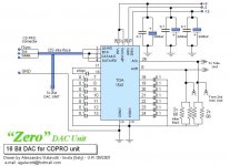
I am intending to build the 2 x TDA1541A (S1- is I can find some). I planned to use the I2C from my CD-PRO2 and connect it directly into the two TDA1541A, like the way the "ZERO" of Allessandro Galavotti is designed.
However looking at the attention that re-clocking usually has in the discussions on this forum, I wonder if a Zero dac can be build without re-clocking.
I would appreciate your help.
Thanks!
Peter
On every thread regarding zero oversampling DAC's re-clocking is a major item.
I am intending to build the 2 x TDA1541A (S1- is I can find some). I planned to use the I2C from my CD-PRO2 and connect it directly into the two TDA1541A, like the way the "ZERO" of Allessandro Galavotti is designed.
However looking at the attention that re-clocking usually has in the discussions on this forum, I wonder if a Zero dac can be build without re-clocking.
I would appreciate your help.
Thanks!
Peter
Attachments
Hi Peter,Peter K said:Hi,
On every thread regarding zero oversampling DAC's re-clocking is a major item.
I am intending to build the 2 x TDA1541A (S1- is I can find some). I planned to use the I2C from my CD-PRO2 and connect it directly into the two TDA1541A, like the way the "ZERO" of Allessandro Galavotti is designed.
However looking at the attention that re-clocking usually has in the discussions on this forum, I wonder if a Zero dac can be build without re-clocking.
I would appreciate your help.
Thanks!
Peter
Reclocking is not a must but it was done by Kusunoki in his NON-OS TDA1543 DAC.
I found the sound became more analog and got more depth in the soundstage. Also instruments got more "separated". Most important is that the clock used for the reclocking is low jitter.
")
Low Jitter clock
Hi Elso,
I tried the asynch reclocking using a 66MHz oscillator (similar in construction to guido's low jitter) and it seemes to work fairly well, certainly the reclocked bck line in the cd player seemed to have less overshoot when examined using a scope. I have not listened for an improvement yet and will be doing so shortly. I am curious to hear about your experiences in TDA1543. What about reclocking data? I noticed that the waveform for data looked pretty much the same with and without recloking BCK.
How does one determine if the clock is low jitter? The 66 MHz osc. I have I purchased from a general electronics shop.
One other thing: I built the KWAK 5 clock using AD8561 and measurement wise it seems very similar to the guido tent osc. in cleanness of the clock output (at 11.xxMHz) as measured on my 20MHz scope. For sound, they actually are virtually identical. Good sound from both.
Regards
Ryan
Asynchronous Reclocking
Hi Ryan,
Jitter improvement can not be seen on the scope.
Kusunoki reclocked only the Bitclock and the LATCH (Wordsync) but I found reclocking the DATA also is worthwhile. In fact not reclocking the latter gave a tremendous loss of definition of the sound. The above pictured sound-experiences in post #3 are for the TDA1543. Strangely enough asynchronous reclocking gave more improvement for the AD1865. More jitter sensitive chip???
If a ready made cantype oscillator is low jitter may be seen from the specs. Be careful, jitter is specified as peak-peak, r.m.s. or 3-Sigma...But consider specs a just a indication. Final test is listening.
You could try version 6 of the KWAK-CLOCK as this works well in a Philips player. This will give more bass slam. I suppose you have a Philips CDP as your frequency is 11.2896 MHz.
All clocks have different sonic signature. Lately I tried Guido's , Netaudio and mines in my Philips CD-650. If you hear no difference go for the cheapest solution, I would say.
Peter,
You better connect your dac to the i2s bus and not to the i2c bus... Otherwise there will not be much sound.
Have a look at the 2*tda1541 post from a while back. If you want to go for two tda's it might be usefull. I myself have little time at the moment, but i am still progressing slowly.
Greetings,
GuidoB.
apropos of jitter
Here's a link to an EDN -- current issue -- on jitter.
http://www.e-insite.net/ednmag/index.asp?layout=article&articleid=CA293235&pubdate=5/1/2003
or the PDF version of the same:
http://a330.g.akamai.net/7/330/2540...-insite.net/ednmag/contents/images/293235.pdf
Here's a link to an EDN -- current issue -- on jitter.
http://www.e-insite.net/ednmag/index.asp?layout=article&articleid=CA293235&pubdate=5/1/2003
or the PDF version of the same:
http://a330.g.akamai.net/7/330/2540...-insite.net/ednmag/contents/images/293235.pdf
<b>Of course</b> jitter improvement can be seen on a scope. How else were you expecting to see it? The only ways I know of visualizing jitter are with an eye diagram on an oscilloscope, or by mixing the signal under test with a signal of known quality and observing the spectrum of the result. Either way, the proof is on the CRT, not in some magical phenomenon.
jwb said:<b>Of course</b> jitter improvement can be seen on a scope. How else were you expecting to see it? The only ways I know of visualizing jitter are with an eye diagram on an oscilloscope, or by mixing the signal under test with a signal of known quality and observing the spectrum of the result. Either way, the proof is on the CRT, not in some magical phenomenon.
Hi,
Like you indicate, you need additional hardware to make jitter vissible. The eye diagram method relies on the analogue processing within the scope (deflection jitter counts here) and has limitted resolution.
However, your suggestion is based on frequency domain measurements, using a low noise reference (and in-phase) oscillator, and low noise mixer.
That will give you a fairly good indication, but the non plus ultra mathod is measuring time (as jitter related to timing).
Therefor I use a wavecrest time domain analyser. I still do not have an unambiguous correlation with TDA and spectral measurements, therefor I stick with TDA.
all the best,
As always, I am envious of anyone with access to time-domain instruments. However I will note that inexpensive techniques can also be productive. For example, you can measure random jitter by simply building two devices under test, mixing their output in-phase, and measuring the spectrum. No stable timebase is needed, although the quality of the PLL will be evident.
I am in awe that modern instruments have such stable timebases, and PLLs operating up to tens of gigahertz. This stuff isn't covered in Horowitz and Hill!
I am in awe that modern instruments have such stable timebases, and PLLs operating up to tens of gigahertz. This stuff isn't covered in Horowitz and Hill!
Hi, I have this marantz cdp with a Philips cdm12.1/15 transport. Do you know if this transport has a I2S output? I plan to build a non-oversampling dac and I am wondering if I need a CS8412 for receiving the signal from the digital output or I can get it from a I2S.
Miguel
Miguel
Miguel,
Depends on the decoder inside: what is it and does it have the dig. filter included. And it depends how it is setup, maybe it is setup to sent the info to the dac in another format then i2s (then you could deside to use a non i2s dac, maybe TDA1543A instead of TDA21543).
Since it all depends on what is inside and i don't have the schematic, you should open it up and see if you can figure out what is there. Some parts could be on the bottom side of the pcb as SMD chips! Or find the schematics.
Greetings,
GuidoB
jwb said:As always, I am envious of anyone with access to time-domain instruments. However I will note that inexpensive techniques can also be productive. For example, you can measure random jitter by simply building two devices under test, mixing their output in-phase, and measuring the spectrum. No stable timebase is needed, although the quality of the PLL will be evident.
I am in awe that modern instruments have such stable timebases, and PLLs operating up to tens of gigahertz. This stuff isn't covered in Horowitz and Hill!
Hi
TDA's measure time and therefor have very acurate triangle wave generators and timers
Mixers: The resulting spectrum is dominated by the worst (most noisy) source, so better make sure the refenece clock / PLL is clean......
all the best
Here you are,The third kusunoki DAC...The 74AC74 + CLOCK is for the asy re-clocking
An externally hosted image should be here but it was not working when we last tested it.
This way of drawing means that pins 1,4,10 and 13 are connected to 5V, just as pin 14 of course. Please check the pins that are connected to ground to see the difference in symbols. Pin 7 has the ground symbol and pins 6 and 8 are Not Connected.
Don't know why it was drawn so confusing. Have seen it before and when such schematics are copied they start being even more confusing.
Don't know why it was drawn so confusing. Have seen it before and when such schematics are copied they start being even more confusing.
cd-reclock schematic
Thank you Jean Paul
Do you mean, pin 1, 4, 10, 13 and pin 14 should be connected all together to same 5v voltage and pin 7 is the gound?
Furthermore, from the schematic, the JX07 seems to be a 50MHZ oscillator, What is the function of that oscillator?
Thanks
Thank you Jean Paul
Do you mean, pin 1, 4, 10, 13 and pin 14 should be connected all together to same 5v voltage and pin 7 is the gound?
Furthermore, from the schematic, the JX07 seems to be a 50MHZ oscillator, What is the function of that oscillator?
Thanks
Re: cd-reclock schematic
Yes.
It is the 50 MHz clock ( canned oscillator ) for the asynchronous reclocker as implemented in that DAC. If you go that way make sure you use a low jitter module and shield the reclocking circuit like one has to do with RF electronics. Please bear in mind that whatever you do chances are high that stray RF in the order of a few hundreds of MHz will creep into your amp.
There are a few variants of the same DAC without the reclocker as well. Just do a Search here on Kusonoki.
TKK1010 said:Do you mean, pin 1, 4, 10, 13 and pin 14 should be connected all together to same 5v voltage and pin 7 is the gound?
Yes.
TKK1010 said:Furthermore, from the schematic, the JX07 seems to be a 50MHZ oscillator, What is the function of that oscillator?
It is the 50 MHz clock ( canned oscillator ) for the asynchronous reclocker as implemented in that DAC. If you go that way make sure you use a low jitter module and shield the reclocking circuit like one has to do with RF electronics. Please bear in mind that whatever you do chances are high that stray RF in the order of a few hundreds of MHz will creep into your amp.
There are a few variants of the same DAC without the reclocker as well. Just do a Search here on Kusonoki.

- Status
- This old topic is closed. If you want to reopen this topic, contact a moderator using the "Report Post" button.
- Home
- Source & Line
- Digital Source
- Re-clocking a must?