Any word on when Tachyon might produce another run of the SDTrans384?
I asked them their plan for the next release.
They are preparing it and hopefully going to start it by the end of this month.
Please send your reservation and estimate request to Tachyon.
Hi, Mihai!
I asked Chiaki the delay. He has never measured it and me neither.
As only a simply divider circuit is implemented in the FPGA, the delay must not be so large.
I will measure it by a scope in a few days.
Bunpei
From your answer may presume that the final FPGA stage consists in three flip-flops with I2S signals as inputs and MCLK as reclocker signal?
If this is the case then delay is under 5nS
Hi, Mihai!
I'm sorry that my previous answer was too simplified.
Precisely speaking, a rising edge of MCLK is a start point of series of digital processing.
After a certain delay resulted from FIFO-out processing, a first bit data appears. At the middle of the period of bit data assertion, a rising edge of the corresponding bit clock appears. Therefore, 1/ (64 x fs x 2) + alpha delay in all. However, the alpha is, approximately, a few ns, within the first half of MCLK period, namely, high level period.
So, it is not an "INVERTED MCLK" relation.
Would you observe the relationship with your oscilloscope in order to make it clear?
Bunpei
Hi, Mihai!
I'm sorry that my previous answer was too simplified.
Precisely speaking, a rising edge of MCLK is a start point of series of digital processing.
After a certain delay resulted from FIFO-out processing, a first bit data appears. At the middle of the period of bit data assertion, a rising edge of the corresponding bit clock appears. Therefore, 1/ (64 x fs x 2) + alpha delay in all. However, the alpha is, approximately, a few ns, within the first half of MCLK period, namely, high level period.
So, it is not an "INVERTED MCLK" relation.
Would you observe the relationship with your oscilloscope in order to make it clear?
Bunpei
Thank you for explanations.
I didn't expected inverted I2S signals at the output of the SD transport.
In fact, I believe that inverted MCLK is required in sync mode by the 9018 DAC for "nullifying" all the delays that are introduced by the I2S source.
In this case, the DAC will trigger I2S signal processing on the falling edge of the MCLK clock giving approx 1/2 MCLK time for the source to put all the data on the input of the DAC.
It doesn't maters if the DAC MCLK is inverted or the clock provided to the SDtrans is inverted (derived from the DAC clock), as the same logic will apply.
Last edited:
A Japanese audio shop Tachyon is accepting an order for the second batch of SDTrans.
If you want to buy some, please contact to Mr. Yamasaki, an owner of the company.
jack<at>mtc<dot>biglobe<dot>ne<dot>jp
They say the number of the batch is 30 and a delivery is expected on February.
If you want to buy some, please contact to Mr. Yamasaki, an owner of the company.
jack<at>mtc<dot>biglobe<dot>ne<dot>jp
They say the number of the batch is 30 and a delivery is expected on February.
SDTrans384
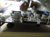
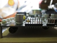
I got the Sdtrans384 working. It is powered by 4 c cells. I tried 3 but the LCD wasn't visible. I have the I2S output connected to a TPA Teleporter. I am listening to 16/44 for the most part. I have some of my own vinyl rips that are 24/192 so will need to get some high res files to check out what it can really do. It sounds really nice. Very full sounding, like sacd. Great job on the excellent digital source. Thanks guys!
I got the Sdtrans384 working. It is powered by 4 c cells. I tried 3 but the LCD wasn't visible. I have the I2S output connected to a TPA Teleporter. I am listening to 16/44 for the most part. I have some of my own vinyl rips that are 24/192 so will need to get some high res files to check out what it can really do. It sounds really nice. Very full sounding, like sacd. Great job on the excellent digital source. Thanks guys!
Attachments
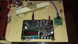
I am using a fully discrete series regulator, 500mA, that is being fed by a good raw power supply and a toroid transformer. I think this is better than batteries. Batteries are noisy and do not have low output impedance.
Hi,
I just received shipping confirmation of my SD Trans from Tachyon. I hope to have it soon! Can anyone point to a great ps scematic to use with it?
My 5V psu for sdtrans is the same as CeeVee, too
In my experience, very good 5V PSU and PPS bypass capacitor mod was big step forward...
And pay attention to reducing or eliminating common mode noise.
")
SDTrans384
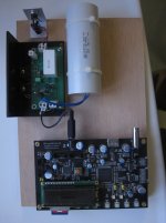
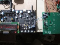
I replaced the batteries with a TPA Placid and it sounds much better. I looked into getting the TI TPS7A4700 evaluation board that Bunpei suggested but it requires hotair mounting the smd parts. I haven't done that before and dont have the tools to do that. Any schematics for a really good regulator I can solder?
What are people doing for a case? The face looks like it needs a thin material to make the card slot easy to use and needs to let the leds be viewable.
Has anyone got a remote set up to contol their SDTrans384?
How long can the I2S wires be before there are issues. I am connecting to a Teleporter so it isnt too hard to setup but it would be good to know how far back to the back panel.
I will get the PPS caps from Bunpei to improve the sound.
This thing is a real step up from the shigaclone cdp I was using before.
Thank you again for the great SD player.
Hi, SDTrans384 users and those who are interested in a SDTrans384 board kit!
When you want to know its availability or its price, please contact to Mr. Yamazaki of Tachyon in Japan by e-mail. His address is;
jack<at>mtc<dot>biglobe<dot>ne<dot>jp
The second batch released by them was sold out last month. He will accept a reservation for the next batch.
If you want to get technical details in English or you want to purchase some components only available in Japan, please send your usual e-mail to me.
bunpei<at>ta2<dot>so-net<dot>ne<dot>jp
(Please do not use PM on this forum for this purpose. I appreciate your real name.)
Anyway, I was much pleased with recent posts by SDTrans users.
To bikerboy,
As for TI TPS7A4700 evaluation board, it is a finished product of 20 USD/each including Fedex fee. You do not have to solder the chip at all.
Some Japanese DIY audio hobbyists are distributing bare board kits for the regulator. Users of those boards say they can deal with the chip by using a usual solder and a soldering iron though a good soldering skill is required.
Tachyon is considering a possible distribution of optional remote control unit for SDTrans.
Bunpei and some other users in Japan developed their own remote control receiver by using an Arduino micro-controller board, Apple IR remote and modified Hifi-duino code.
Please keep the length of I2S wiring as short as possible. The maximum allowable length depends on the fs of your source. If the length is more than 10 cm or 4 inches, it's good to use such a LVDS extension method as TPA Teleporter.
I hope you enjoy music with SDTrans!
Last edited:
....
As for TI TPS7A4700 evaluation board, it is a finished product of 20 USD/each including Fedex fee. You do not have to solder the chip at all.
Some Japanese DIY audio hobbyists are distributing bare board kits for the regulator. Users of those boards say they can deal with the chip by using a usual solder and a soldering iron though a good soldering skill is required.....
I have two of those...will try in comparison with Salas BIB..will let you know subjective results
.
- Home
- Source & Line
- Digital Source
- MicroSD Memory Card Transport Project