Weird subject name huh? Honestly speaking I had a hard time coming up an appropriate subject name because.... I simply dont know how to phrase it!
Alright. Here's what im curious about.
Assuming im bypassing a certain Vcc pin with a say, .1uF film cap that is soldered right next to the pin. The Vcc is connected to a 5V line. (wire soldered onto the pin)
Does the placement of the 5V wire play a major role here? Meaning physically, the orientation of the connection is as follows.
5V wire soldered to bypass cap. Bypass cap soldered to Vcc pin
or
5V wire soldered to Vcc pin. Vcc pin soldered to bypass cap.
Must the voltage line come in physical contact with the the bypass cap first so that the "downstream" is ripple-free? Or does it not matter as long as the cap is close to the Vcc pin.
For the optimum decoupling - I would go with this: A decoupling cap soldered directly (as close as possible) to the IC's Vss (Gnd) pin, connected with the Vcc pin via a wire, and then, Vcc pin is connected to the power supply via a ferrite bead.
Sorry if this isn't a direct answer to your question...
Cheers!
Sorry if this isn't a direct answer to your question...
Cheers!
alright I think you guys misunderstood my question!
though I am partly to be blamed for not being concise enough.
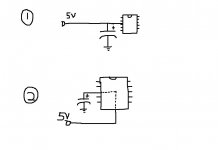
i've attached a picture.
case 1: 5V line in physical contact with cap first before Vcc
case 2: 5V line in physical contact with Vcc first before cap.
Assuming both caps are equally close to the IC in both scenarios,
would case 1 and 2 make a difference?
though I am partly to be blamed for not being concise enough.
i've attached a picture.
case 1: 5V line in physical contact with cap first before Vcc
case 2: 5V line in physical contact with Vcc first before cap.
Assuming both caps are equally close to the IC in both scenarios,
would case 1 and 2 make a difference?
Attachments
- Status
- This old topic is closed. If you want to reopen this topic, contact a moderator using the "Report Post" button.