Hi John
please put me on the order list!")
Have you seen my post #109 and#110?
The main difference will be that the QA-550 is universal mid-fi design and John does real high-end!
If you look closely at the picture of the QA-550 there is a funny mistake with the labeling! Who has seen it?
please put me on the order list!
Have you seen my post #109 and#110?
The main difference will be that the QA-550 is universal mid-fi design and John does real high-end!
If you look closely at the picture of the QA-550 there is a funny mistake with the labeling! Who has seen it?
Yes John,
The advantages of avoiding any mechanical moving parts
- no spurious PS current draws from servos & motors which bleed back into the clock PS (but logic gates firing can also cause PS glitches - so your DSP chip could also introduce some PS noise. I noticed you have avoided DSP processing as much as possible by supporting only WAV)
- no need for the error-correcting/extrapolation of real-time CD laser readers (& the associated problems)
In doing that you've addressed the main shortcomings of mechanical transports.
Your implementation of the clock signal distribution is interesting BUT I still think that you need to check the jitter at the DAC in order to prove that you have achieved your goal.
Tolu said:
If you look closely at the picture of the QA-550 there is a funny mistake with the labeling! Who has seen it?
Are you talking about the constant power draw caused by the "NO/OFF" button?
Javin5 said:Is anything known about the contact reliability of these SD-cards? How many times can they be inserted?
They appear to be rated typically for 10,000 or more insertion/removal cycles.
Hi jkeny,
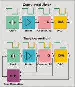
I attached a block diagram that may clarify the problem (cumulated jitter) and a possible solution (time correction). Best comparison would be that of feedback in an analogue circuit
I have been trying to say that sample timing jitter (DAC output) is most important parameter, low master clock jitter alone is not the solution (top block diagram). So inserting a low jitter master clock is fine, but basically provides only marginal improvement since DAC jitter contribution is usually much higher as that of the master clock, followed by flip-flops / counters and clock buffers.
Sample timing jitter (DAC output / during D/A conversion) translates to audible digital artifacts, by using selected highly critical test tracks, the effects of sample timing jitter can be magnified. Without time correction these digital artifacts remain audible. With the time correction enabled, these audible digital artifacts vanish completely.
Measuring these extreme low jitter levels is difficult (here it can only be measured at a NOS DAC unfiltered output using a suitable test signal). Modern DACs are problematic as they don't provide a suitable feedback signal (integrated switched-capacitor filters). Connecting a test probe already affects measurement too (capacitive load + introduced ground loop).
Your implementation of the clock signal distribution is interesting BUT I still think that you need to check the jitter at the DAC in order to prove that you have achieved your goal.
I attached a block diagram that may clarify the problem (cumulated jitter) and a possible solution (time correction). Best comparison would be that of feedback in an analogue circuit
I have been trying to say that sample timing jitter (DAC output) is most important parameter, low master clock jitter alone is not the solution (top block diagram). So inserting a low jitter master clock is fine, but basically provides only marginal improvement since DAC jitter contribution is usually much higher as that of the master clock, followed by flip-flops / counters and clock buffers.
Sample timing jitter (DAC output / during D/A conversion) translates to audible digital artifacts, by using selected highly critical test tracks, the effects of sample timing jitter can be magnified. Without time correction these digital artifacts remain audible. With the time correction enabled, these audible digital artifacts vanish completely.
Measuring these extreme low jitter levels is difficult (here it can only be measured at a NOS DAC unfiltered output using a suitable test signal). Modern DACs are problematic as they don't provide a suitable feedback signal (integrated switched-capacitor filters). Connecting a test probe already affects measurement too (capacitive load + introduced ground loop).
Attachments
Hi Tolu,
I think we might have a solution, this puts some restrictions on track names and requires an identifier file (gapless.txt) to be included in the directory that holds the tracks (WAV files) that are part of a gapless album.
Any progress with gapless playback?
I think we might have a solution, this puts some restrictions on track names and requires an identifier file (gapless.txt) to be included in the directory that holds the tracks (WAV files) that are part of a gapless album.
Hi jonners,
The card holder will wear-out first, so I made it replaceable (separate PCB).
They appear to be rated typically for 10,000 or more insertion/removal cycles
The card holder will wear-out first, so I made it replaceable (separate PCB).
Hi guglielmope,
The SD-player supports Philips I2S, 32 bits / frame only.
also EiAj is supported (TDA1545, AD1865 etc.) or only I2s?
The SD-player supports Philips I2S, 32 bits / frame only.
mobile phone as the infra red remote control
@all:
john has designed this sd-player with respect to very low interference levels, very low jitter, etc.
following this objective, the user interface of the sd-player is very minimalistic and the user has a relatively poor gu-interface and functionality compared to a pc based media center interface.
i was wondering if somebody can write an application for mobile phones (iphone, sony-ericsson, nokia, windows mobile, symbian, ...) as "ir-remote control" for this sd-player. the application could provide an archive system with nice and attractive user and graphic interface. so by navigating through the archive on the mobile phone the user can select the desired cd and track and send just the ir-command to the sd-player.
provided the playing time (length of the tracks) is known in the database, even individual play lists can be put together by the user and stored in the cell phone.
@john:
if you provide the sd-player with a simple bi-directional ir-functionality, would this have a high negative impact on the interference and jitter levels?
if you could send some key information from the sd-player such as playing time, etc back to the ir-remote control data base (mobile phone), a very nice and accurate remote control application could be done.
cheers
mamal
-ecdesigns- said:Hi jkeny,
I attached a block diagram that may clarify the problem (cumulated jitter) and a possible solution (time correction). Best comparison would be that of feedback in an analogue circuit
I have been trying to say that sample timing jitter (DAC output) is most important parameter, low master clock jitter alone is not the solution (top block diagram). So inserting a low jitter master clock is fine, but basically provides only marginal improvement since DAC jitter contribution is usually much higher as that of the master clock, followed by flip-flops / counters and clock buffers.
Sample timing jitter (DAC output / during D/A conversion) translates to audible digital artifacts, by using selected highly critical test tracks, the effects of sample timing jitter can be magnified. Without time correction these digital artifacts remain audible. With the time correction enabled, these audible digital artifacts vanish completely.
Measuring these extreme low jitter levels is difficult (here it can only be measured at a NOS DAC unfiltered output using a suitable test signal). Modern DACs are problematic as they don't provide a suitable feedback signal (integrated switched-capacitor filters). Connecting a test probe already affects measurement too (capacitive load + introduced ground loop).
OK, you've mentioned a number of jitter reducing techniques:
-
-In order to maintain low (bit) clock jitter levels at the DAC chip internal circuits, I attenuate the master clock amplitude to approx. 400mV, and create a low load impedance (approx. 33 Ohm), this is possible with both TDA1543 / TDA1541A as these have TTL-compatible current steering inputs.
The 1.4112 MHz bit clock is then synchronously reclocked with a single high-speed D flip-flop (160 MHz ... 4 GHz), using the second master clock output. The clock signal is then fed to the DAC chip using a dynamic jitter attenuator circuit. It dynamically manipulates exact moment of triggering in order to achieve even lower sample timing jitter.
- Is the time correction you now mention actually the same as the dynamic jitter attenuator?
- Can this only be done with the TDA DACs or is it applicable to others?
- Can you say what test tracks show up timing jitter clearly?
- I'm not trying to be critical here but you're very aware, I know, that changes in how a track sounds do not necessarily mean lower jitter. The sound of jitter is very elusive - are you using the test tracks from here?: http://hddaudio.net/?p=393
-ecdesigns- said:Hi guglielmope,
The SD-player supports Philips I2S, 32 bits / frame only.
Hello EC,
I'm aware that you use I2S with 32 bits/frame and 1,4Mhz for BCK of the TDA1543, but is this format and BCK frequency going to apply also for the TDA1541A in case someone would like to use the I2S generated by the SD card player in combination with the TDA1541A?
Hi Luxury54,
TDA1541A (like TDA1543) accepts Philips I2S, 32 bits / frame, so the TDA1541A will work without problems. The TDA1541A can also provide a suitable feedback signal required for time correction.
I'm aware that you use I2S with 32 bits/frame and 1,4Mhz for BCK of the TDA1543, but is this format and BCK frequency going to apply also for the TDA1541A in case someone would like to use the I2S generated by the SD card player in combination with the TDA1541A?
TDA1541A (like TDA1543) accepts Philips I2S, 32 bits / frame, so the TDA1541A will work without problems. The TDA1541A can also provide a suitable feedback signal required for time correction.
Aha, John, I see now where this I2S jitter reduction idea emanated from: http://www.diyaudio.com/forums/showthread.php?postid=369849#post369849
A fellow countryman of yours!
And this is where you get your jitter figure of 400 Femto secs rms!
Nobody on that thread built & measured the circuit though - have you any further info?
A fellow countryman of yours!
And this is where you get your jitter figure of 400 Femto secs rms!
Nobody on that thread built & measured the circuit though - have you any further info?
OK EC,
It seems your circuit goes beyond Henk's in that yours dynamically adjusts the timing - can you tell me the details of how this works i.e for a late BCK signal, how does the I2S circuit work to deliver this on-time?
Does it work something like: the 1.2V bias voltage moves slightly with the jitter (BCK duty cycle) & this moves the pos & neg firing point of BCK, advancing or retarding it? The trick being to get the exact correct adjustment or it introduces more jitter. How sensitive is this circuit to thermal or other drifts?
- Status
- This old topic is closed. If you want to reopen this topic, contact a moderator using the "Report Post" button.
- Home
- Source & Line
- Digital Source
- Lossless SD-card player