I have a few questions regarding the analog supply regulator in my cd player. It doesn't seem to work very well, there is a considerable ripple voltage (40 mVpp) across the output.
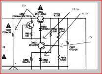
If you look at the enclosed schematic, the 2SK246 should work as a CCS but there is only 0,9V across it in normal operation.
When I measure the voltage across R851 there is a big sawtooth. This would be normal for such a low voltage. I lowered the value of R853 to give the jfet a little more headroom and then the ripple voltage is gone completely (on my scope view that is).
It seems that the Marantz has a major design flaw here. I checked service manuals for other players and they all seem to have the same problem: output voltage is 11.4 V. Vbe for Q852 is about 1.2V, then there is the seemingly unnecessary D858 eating up about 0.5V, the voltage across R851 is 0.3V, leaving only 1V for Vds of the jfet.
This is far too low (check 2sk246 datasheet, you'd need at least 2V for saturation).
Has anyone noticed this before? Solutions would be:
- omitting D858, but perhaps it has a function during shutdown or start up. I could replace with a schottly (like bat85) to gain some headroom
- lowering the output voltage for the HDAMs. Looking at the schematic they wouldnt mind too much. Perhaps a slight increase in common-mode distortion.
- increasing the value for C851. Of course.
It seems sad that the designers at Marantz made such stupid mistake in al lot of their equipment.
Am I missing something?
Attachments
The input volage, measured with multimeter is 14,3 V. Then there is the 0,35V ripple voltage, so the minumum value of the input voltage may be about 14.1 V or so.
This is as specified by Marantz and is similar for other type of players.
The voltage across the zener is 5.6V. Across the negative input (base of Q853) is 6.3V. Collector voltage is 13.1V.
Note that the power transistor is a darlington with about 1.2V Vbe.
So, with such a low input voltage the reg just doesn't work. Marantz are stupid!
BTW: the regulator is not floating, but connected to ground (not shown).
Something doesn't ring true with this, and from what you say I agree. It needs a higher input voltage. I know service manuals can be wrong... quoted voltages and so on, so all I can suggest is start at the input side. Don't overlook anything.
1. Correct mains voltage on primary ? trx tappings OK if there are any.
2. Whats the secondary voltage, does it calculate out to what you measure DC wise.
3. Any diodes OC in the bridge.
4. Safety resistor gone high etc.
A 35 volt cap wouldn't normally be specified when less would do !
Altering the value of C851 will have no effect on the output voltage, and even doubling it will only marginally reduce the ripple across it.
I agree. But I am pretty sure that it works as intended. The only thing that maybe off is the secondary voltage of the transformer. It is not pssible to verify this as this voltage is not specified.
I note however that the voltage could not be as high as 20V or so. It is a linear reg, hence the dissipation in the power transistor equals the voltage drop times the current, which is about 400 mA.
With my original values (less than 3V voltage drop) the transistor gets only lukewarm. If I lower the output voltage to 9.3 V (5V drop, corresponding to a input voltage of 16,4 for the targeted output voltage of 11.4V), the heatsink is about 55C, which would be by far the hottest of al heatsinks.
I don't know why Marantz put in those 4700 uF/40V caps which have too low capacitance and a too high voltage rating. Fortunately there is sufficient space to place like 22000 uF caps there (I will probably go for CRC though).
I would be interested to hear what values other people measure in their equipment (like SA11, SA7001, SA8400 and probably more). Specially across the secondaries and the input caps.
Thanks
Odd indeed. I know only 0.5 a volt difference in input voltage will make the difference between it regulating correctly or not at all. It's on too much of a knife edge. How about using a "super beta" transistor... not a darlington... for the series pass element ( can't think of any type numbers off the top of my head ) and omit the diode ? That would gain you some headroom.
What you measure calculates back correctly, ignoring base current.
5.6 across the zener will give around 6.3 on the base of Q853. That in turns gives 1.9ma through R854. That gives 5.2v across R853 which gives a total of 11.5volts... the output voltage.
Could the series pass transistor be faulty at all, they can fail in strange ways sometimes, going low gain or something weird.
Sure your mains voltage is OK ? compared to what the tranny says. 55 degrees is "cool" for commercial equipment, you can go higher than that... not saying it's good design mind you.
- Status
- This old topic is closed. If you want to reopen this topic, contact a moderator using the "Report Post" button.
- Home
- Source & Line
- Digital Source
- marantz cd players, analog supply is flawed