Hi MrSlim,
Welcome to the forum, this is a great place!
Sorry about the board, but it was claimed by someone else about an hour before you posted.
Which design are referring to? The schematic for the first DAC is in post #7 and the one for the above SRC DAC is in post #41. I haven't made a schematic for the above power/output board.
Passive I/V converter
He Guys,
I searched lately for I/V converter for PCM 1794. And even wrote to TI with question about passive-resistor I/V. Results are mixed. TI answered, that resistor conversion will degradate audio signal and similar conclusion was made at " DAC final" page. Moreover, it was also concluded, that using anly one current output will significantly increase THD in audio signal. Opposite results was reported with using PCM 63 DAC.
I will upgrade my Shanling SCD 300, which is equipped with tube stage. So I am tempted to omitt all op amps and use resistor conversion and tube amplification. Do you have any experience with audio test of different I/V converters applied for PCM 1794 or 1792?
Regards
inconsistencies???
hello,
an impressive design, to say the least! i'm working on a similar design, but using a df1704+(2x)pcm1704... i'm curious, however, about certain aspects...
first, you have the DIR9001 set with PSCK[1:0]=11, meaning the output bit clock is running at 512Fs. however, the datasheet of the ASRC4192 states that its input bit clock, when running as a slave as yours is set to do, can run up to only 128Fs.
second, your 192/96 switch doesn't make sense. with the bit clock in master mode, MODE[2:0]=011 would give Fs(out)=RCKI/256=96kHz and MODE[2:0]=010 would give Fs(out)=RCKI/512=48kHz.
please correct me if i'm interpreting this information incorrectly.
thanks!
~ brad.
Hi Brad,
It's been a long time since I messed with this project, so I had to go back over the data sheets and schematic to refresh my memory.
I'm not an expert in this digi stuff, so please forgive me if I am just completely wrong.
About your first point, the DIR9001 is being used in PLL mode and the output is at Fs (48kHz in my case). SCKO is at 512Fs, but it's not even being used.
And your second point about the 96/192 switch is absolutely correct. I just now realized this after going over everything again. The toggle should have been set up like.....
MODE2=0
MODE1=1/0 toggle
MODE0=1
and not.....
MODE2=0
MODE1=1
MODE0=1/0 toggle
It's been a long time since I messed with this project, so I had to go back over the data sheets and schematic to refresh my memory.
i'm curious, how does it sound?
")
~ brad.
Hello Anonymous1, I saw your design and I am tempted to make similar one. Did you make the PCB yourself? Also I have the PCM-1792A and can it be used instead of the PCM-1794 which you have used?
Thanks for your time.
Yes, I made the board by hand.
I think the PCM1792's modes need to be serial controlled, where the PCM1794 is hardware controlled. Unless you plan a microcontroller setup, I would try to obtain the PCM1794A.
Hi Brad,
It's been a long time since I messed with this project, so I had to go back over the data sheets and schematic to refresh my memory.
I'm not an expert in this digi stuff, so please forgive me if I am just completely wrong.
About your first point, the DIR9001 is being used in PLL mode and the output is at Fs (48kHz in my case). SCKO is at 512Fs, but it's not even being used.
And your second point about the 96/192 switch is absolutely correct. I just now realized this after going over everything again. The toggle should have been set up like.....
MODE2=0
MODE1=1/0 toggle
MODE0=1
and not.....
MODE2=0
MODE1=1
MODE0=1/0 toggle
Hi
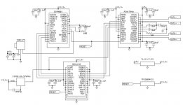
I just need the SRC4192 to be at 96, is the schematic in my image are update to right way for 96 ?
There is 3 reset tag in your schematic, where do we connect them ?
Do that schematic need to be update and do it match your pcb image ?
Thanx
Paul
Attachments
Last edited:
Hi
I just need the SRC4192 to be at 96, is the schematic in my image are update to right way for 96 ?
There is 3 reset tag in your schematic, where do we connect them ?
Do that schematic need to be update and do it match your pcb image ?
Thanx
Paul
Hi Paul,
Yes, that schematic is the one I use for 96kHz.
The 3 reset points are all connected together. It's one TPS3809K33 that controls the reset pin on the PCM1794A and the SRC4192.
- Status
- This old topic is closed. If you want to reopen this topic, contact a moderator using the "Report Post" button.
- Home
- Source & Line
- Digital Source
- Micro DIR9001 + PCM1794A DAC