I bought a used Sony DVP-S7700 for $145..
a new khs-180a laser block itself is $121.99!
for anyone not familiar with this player check out what $145 has get you:
clock:
digital psu which fits within its own shielded enclosure in chassis:
analog psu:
photo kind of makes transport mechanism look cheaper than what it is..though not quite the scd-1/777es (also using khs-180a), this mechanism is a nice one..as though that means anything..
laser block switch out wasn't difficult at all.. I got about 1500hrs out of the used one.. and replaced with spare I had for 777es.
a new khs-180a laser block itself is $121.99!
for anyone not familiar with this player check out what $145 has get you:
An externally hosted image should be here but it was not working when we last tested it.
clock:
An externally hosted image should be here but it was not working when we last tested it.
An externally hosted image should be here but it was not working when we last tested it.
digital psu which fits within its own shielded enclosure in chassis:
An externally hosted image should be here but it was not working when we last tested it.
analog psu:
An externally hosted image should be here but it was not working when we last tested it.
photo kind of makes transport mechanism look cheaper than what it is..though not quite the scd-1/777es (also using khs-180a), this mechanism is a nice one..as though that means anything..
laser block switch out wasn't difficult at all.. I got about 1500hrs out of the used one.. and replaced with spare I had for 777es.
An externally hosted image should be here but it was not working when we last tested it.
An externally hosted image should be here but it was not working when we last tested it.
An externally hosted image should be here but it was not working when we last tested it.
Major companies generally don't take on PCBs with grid references unless they've proved all the blocks. This particular design has probably gotten the advantage of resolving all the issues from rev 1.
If you can access the blind vias on layers 3 and 5 then you can do anything! How do you plan to hack this, I'm intrigued?
If you can access the blind vias on layers 3 and 5 then you can do anything! How do you plan to hack this, I'm intrigued?
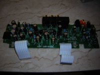
I'm not that advanced! I just made this stupid wire harness connecting digital psu to main digital board. I had to switch out original 12 pin header on main board with Hi-Rose one to get correct fit. It's the only reason I've got digital board out at all. I'm not planning anything else with that board..at least for time being.
I will do some things with the dac/analogue out pcb though.. it seems a good board to experiment with as it is easy to disconnect, get in and out..
(and no I didn't botch top layer pads in getting out 12 pin header..honest..though it looks that way in top photo..a few of 12 pins connect to nothing at all)..that would really suck if I took out a via connecting a layer 3 or 5! everyone check out what I just ruined for $145!)
An externally hosted image should be here but it was not working when we last tested it.
*edit
(and no I didn't botch top layer pads in getting out 12 pin header..honest..(well maybe one--just looked 5x--via is still intact and connects to bottom layer) : / ..2 of 12 pins connect to nothing..that would really suck if I took out via connecting a layer 3 or 5! yes indeed. "everyone check out this hack job I did for $145!" It would also be cruel to have a middle layer connecting a 12 pin header directly.. it's top and bottom layer for this one..actually just bottom, top layer pads only.
(and no I didn't botch top layer pads in getting out 12 pin header..honest..(well maybe one--just looked 5x--via is still intact and connects to bottom layer) : / ..2 of 12 pins connect to nothing..that would really suck if I took out via connecting a layer 3 or 5! yes indeed. "everyone check out this hack job I did for $145!" It would also be cruel to have a middle layer connecting a 12 pin header directly.. it's top and bottom layer for this one..actually just bottom, top layer pads only.
*edit
3 of 12 pins connect to nothing.
right.
digital psu in chassis:
3 of 12 pins connect to nothing.
right.
digital psu in chassis:
An externally hosted image should be here but it was not working when we last tested it.
An externally hosted image should be here but it was not working when we last tested it.
i overestimated 1500hrs on used laser. It worked no problem from dec.06 - jun.08, approx. 561 days. I would say 2hr. a day ave. that laser was on is a bit high, 1.5hrs a day ave. is closer. I used sony primarily for white noise meditation cd I use everyday.. so somewhere between 841.5 and 1122hrs before having to change laser, or 28-37% of total laser life if good for 3000hrs, or $34-$45 of cost of new one. take out time I used laser and I got everything else for close to $100....or not.. : p
are khs180a laser blocks good for about 3000hrs?
on side note:
we have sony vpl-vw50 projector with lamp that is supposedly good for 3000hrs. my brother went through 2500hrs in slightly less than a year, almost all playing Xbox. New lamps for those are $250-400! dad was kind of pissed about that one...those lamps are easy to install though...why am I saying this stuff?!
right so the dvp-s7000: here is the audio board:
Digital Filter cxd8505/Current Pulse DAC cxa8055:
+5V/-7V regulators for CP DAC and opamp analog out, use zener diode as reference, dual opamp, and 2sc2275, 2sa985 transistors:
+5V reg for digital filter:
opamp I/V and buffer and carbon film resistors..sony has a thing for carbon film resistors don't they!
(they also have a thing for not decoupling opamp power pins..at least right close to pins..opamps are ~3 inches from reg output cap on ~4-5mm power leads.
the error amps in regs are not decoupled either, save by 1000uF caps at board entry..distance can be seen in top photo in post..the one error amp is about 4inch from those 1000uFcaps..)
incidentally, here is dvp-s7700 audio board (not my photo):
An externally hosted image should be here but it was not working when we last tested it.
Digital Filter cxd8505/Current Pulse DAC cxa8055:
An externally hosted image should be here but it was not working when we last tested it.
+5V/-7V regulators for CP DAC and opamp analog out, use zener diode as reference, dual opamp, and 2sc2275, 2sa985 transistors:
An externally hosted image should be here but it was not working when we last tested it.
+5V reg for digital filter:
An externally hosted image should be here but it was not working when we last tested it.
opamp I/V and buffer and carbon film resistors..sony has a thing for carbon film resistors don't they!
(they also have a thing for not decoupling opamp power pins..at least right close to pins..opamps are ~3 inches from reg output cap on ~4-5mm power leads.
the error amps in regs are not decoupled either, save by 1000uF caps at board entry..distance can be seen in top photo in post..the one error amp is about 4inch from those 1000uFcaps..)
An externally hosted image should be here but it was not working when we last tested it.
incidentally, here is dvp-s7700 audio board (not my photo):
Attachments
I changed 2 error amps in regulators from NJM4580 to OPA2132 and OPA2134, mainly because I bought those opamps a time ago and haven't used them. I decoupled opamp closest to 1000uF caps with TDK C0G FK 0.1uF ceramic across power pins; that blue little cap is perfect size for this (electrolytic in photo is part of filter for diode voltage reference, not opamp decoupling) :
the opamp furthest from 1000uF filter caps I decoupled with a 4.7uF 50V Black Gate N non-polar across pins. It's only 25 degrees with window open and fans blowing when soldering..although possible it just would have been too time consuming to decouple straight from power pins to load GND..much easier this way..though if I remember not quite as effective? I know I read that somewhere but cannot remember why and don't know enough to reason out why on own.
ps: I'm an absolute wuss when it comes to solder fumes..seriously..my freaking lungs hurt!..I run every day and notice difference on days soldering--3 box fans, open window, and stupid mask just don't seem to do it! : p ..lungs feel constricted at point where air enters and I wheeze a bit..I think it's mostly the rosin flux fumes.
metal irons are amazing.. look at those solder joins! ..not perfect work by me but nice shiny joints are definitely easier to get with those irons:
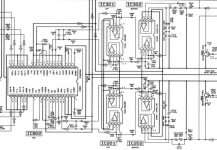
oh, and here is schematic for regs:
An externally hosted image should be here but it was not working when we last tested it.
the opamp furthest from 1000uF filter caps I decoupled with a 4.7uF 50V Black Gate N non-polar across pins. It's only 25 degrees with window open and fans blowing when soldering..although possible it just would have been too time consuming to decouple straight from power pins to load GND..much easier this way..though if I remember not quite as effective? I know I read that somewhere but cannot remember why and don't know enough to reason out why on own.
ps: I'm an absolute wuss when it comes to solder fumes..seriously..my freaking lungs hurt!..I run every day and notice difference on days soldering--3 box fans, open window, and stupid mask just don't seem to do it! : p ..lungs feel constricted at point where air enters and I wheeze a bit..I think it's mostly the rosin flux fumes.
An externally hosted image should be here but it was not working when we last tested it.
metal irons are amazing.. look at those solder joins! ..not perfect work by me but nice shiny joints are definitely easier to get with those irons:
An externally hosted image should be here but it was not working when we last tested it.
An externally hosted image should be here but it was not working when we last tested it.
oh, and here is schematic for regs:
An externally hosted image should be here but it was not working when we last tested it.
I saw one of these on audiogon recently for $40! that is dvp-s7000...: )
here is how audio board ended up for first listen. Note the lousy black epoxy job on coax clock cable. Why on earth didn't I drill a few holes and use cable ties to secure it? Then I could have put epoxy over those if it still moved around too much. It does do the job though, if aesthetics aren't important...but it's pretty bad:
This is how +5V/-7V reg ended for first try. I had these parts on hand, not being used otherwise, save 39K shinkoh:
for analog out I used THS4032 for I/V and LM4562 for buffer/line out. Rubycon 100uF //0.1uF c0g 1206 for current loops to load gnd. 33nF c0g 1206 across power pins, as allowed by small adapter board I used.
To start I kept all values in analog out as sony schematic below.. I used c0g caps for opamp feedback.. I'm wondering how sound would be different if I had used Wima FKP2 film and foil caps for feedback..

decoupling/bypass for digital filter..I added ferrite 601s between Black Gate N electrolytics and 1206 C0G ceramics as close as possible to power pins, for short high frequency AC current loops to gnd plane:
here is how audio board ended up for first listen. Note the lousy black epoxy job on coax clock cable. Why on earth didn't I drill a few holes and use cable ties to secure it? Then I could have put epoxy over those if it still moved around too much. It does do the job though, if aesthetics aren't important...but it's pretty bad:
An externally hosted image should be here but it was not working when we last tested it.
This is how +5V/-7V reg ended for first try. I had these parts on hand, not being used otherwise, save 39K shinkoh:
An externally hosted image should be here but it was not working when we last tested it.
for analog out I used THS4032 for I/V and LM4562 for buffer/line out. Rubycon 100uF //0.1uF c0g 1206 for current loops to load gnd. 33nF c0g 1206 across power pins, as allowed by small adapter board I used.
An externally hosted image should be here but it was not working when we last tested it.
An externally hosted image should be here but it was not working when we last tested it.
To start I kept all values in analog out as sony schematic below.. I used c0g caps for opamp feedback.. I'm wondering how sound would be different if I had used Wima FKP2 film and foil caps for feedback..
decoupling/bypass for digital filter..I added ferrite 601s between Black Gate N electrolytics and 1206 C0G ceramics as close as possible to power pins, for short high frequency AC current loops to gnd plane:
An externally hosted image should be here but it was not working when we last tested it.
Attachments
here are those 1206 c0g feedback caps:
An externally hosted image should be here but it was not working when we last tested it.
Anyone have any goosd luck withh some simple mods, I was going to add som e Capacitance to the P.S. lines, was going to a a Elena 63v 10,000 Lps for filterin off of the R-core, Was wondering if this is going to bee a problem they goy Two 560 uF 200v in series for filtering is the voltage More important ? Was going to add 63v 2,200uf Nichicon FWs on all P.S lines, that what i see on most DACS. I mean does 280 Ufs on the PS. seem low ? let me know what got You some good results! I'm planning on running it To a Outbaord DiY'd minni 24/96 AKM 2496 CS84xx, Ne5532 or a Lm4562 Opamp. But i've heard it said that this DVP. Buy itself can be quite impressive with a couple moidifications. Help PLeasek, Thanks A bunch, And Rock ON!
SWANNY
SWANNY
- Status
- This old topic is closed. If you want to reopen this topic, contact a moderator using the "Report Post" button.
- Home
- Source & Line
- Digital Source
- Sony DVP-S7700: all this for $145 (with photos)