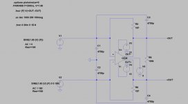
Attached below is a schematic for a discrete I/V stage, intended to be used with the Twisted Pear Buffalo or COD DACs. It uses Nelson Pass' supersymmetry concepts, with a couple of twists of my own. The gain block effectively has 5 terminals - ground sense, Input A and B, Output A and B. In use feedback loops are closed by putting resistors from Output A to Input B and vice versa.
The symmetry of the output is maintained by a separate path that compares the outpoint mid point with ground. In principle, if an application needed the complementary outputs to move centred on some other voltage, this could be fed into the base of Q1 instead.
The schematics have been checked by simulating the extracted Spice file, but not built.
The most important idea is in the next post, which will show how the basic block is used.
By the way, a quoll is an Australian marsupial carnivore, about the size of a cat. I saw them on holiday in Tasmania, and they most attractive. See
Wikipedia for more details.
Attachments
The file attached here shows how the bock would be used.
Note that the dominant pole compensation components are placed before any active devices, at the "virtual earth" points. This removes high frequency rubbish before it encounters any devices that could possibly overload, fixing the major objection to feedback based IV circuits.
For a Buffalo, about 180 Ohms for RF and RF1 should give roughly Red Book levels.
Just a reminder, this has only been simulated, not built!
Attachments
PD,
Clever.")
That's very similar to the "original" counterpoint design I presented in the "Haiku" thread where I took feedback at the bases of the input pairs. I used a folded cascode where you are using a resistor load. I also used a diamond buffer type output stage.
I am sure the cct would work fine. Mine worked very well indeed, but in the end I decided I did not want to use Nelsons IP, and would try to create some of my own.
You will need a way to trim the output offset unless you can match things very very well.
Good work!
Cheers!
Russ
Clever.
That's very similar to the "original" counterpoint design I presented in the "Haiku" thread where I took feedback at the bases of the input pairs. I used a folded cascode where you are using a resistor load. I also used a diamond buffer type output stage.
I am sure the cct would work fine. Mine worked very well indeed, but in the end I decided I did not want to use Nelsons IP, and would try to create some of my own.
You will need a way to trim the output offset unless you can match things very very well.
Good work!
Cheers!
Russ
Good point about the offset.
Because the DC gain is low (about 1) and the impedances very low, the offsets will be dominated by the Vbe mismatches of the differential pairs. If they come from the same batch, I think you would hope for less than 20mV, which should be acceptable for many applications.
If lower offsets than that are needed, the pairs of 47 ohm emitter resistors can be swapped for a trim pot.
I went for resistor loading, rather than folded cascode, as it gives some extra CMRR in the second stage.
Yes, like any opamp used for I/V, this one has a high open loop impedance, and low closed loop impedance.
I tried resistor loading too, but found it did not work as well for me.
Also you would likely need to augment the output devices to retain decent THD into lower impedance loads.
I also would look closely at how the circuit handles the fast slewing of the DAC as well as capacitive loads. This is the one major weakness of direct I/V using massive feedback.
How will the cct react to a short at the output?
Build one and give it a shot.
My discrete SUSY opamp I/V sounds excellent but is essentially the same as a THS4131.
Cheers!
Russ
Russ White said:Yes, like any opamp used for I/V, this one has a high open loop impedance, and low closed loop impedance.
I tried resistor loading too, but found it did not work as well for me.
Also you would likely need to augment the output devices to retain decent THD into lower impedance loads.
Sure - I think Diamante was designed to drive headphones? I wanted to keep things simpler, and save at least one stage by targetting line level loads (although it drives say 600 Ohms very nicely). This is a deliberate trade-off - I didn't want to redo you work from Diamante!
I also would look closely at how the circuit handles the fast slewing of the DAC as well as capacitive loads. This is the one major weakness of direct I/V using massive feedback.
I have studied this extensively, and this is why the compensation caps are in front of the input stages; you literally cannot make this slew rate limit with any signal in the DAC output range, no matter how fast; the dominant pole lies before the first gain stage.
The downside of doing this is that noise floor rises above the pole frequency, but I view this as a viable tradeoff at these signal levels.
Capacitive loads up to several nF are OK. Obviously a big enough load can make it unhappy at high frequencies - but it can drive tens of meters of cable without trouble.
How will the cct react to a short at the output?
As shown, with loss of the magic smoke! In practice, I would put say 50 Ohm stoppers in the output lines to isolate it from cable capacitance, and these will just about save the output devices. This also gives more or less matched impedance drive to STP.
You will have to explain how you accomplish the pre-input filtering without raising the input impedance.
In the scheme you show in you second pic both the negative feedback and the input will be equally shunted to ground.
I just simulated, and this does not produce an effective filter.
I also have tried this with fully symmetrical opamps, it does not work.
To make it work, you need an input resistor after the filter cap. this will raise input impedance.
Also I was not referring to Diamante, to my opamp version of counterpoint.
I will try to dig up a link.
Cheers!
Russ
The caps are not for filtering - they are for stability!
If you want filtering, you add a cap across RF; I have simulated this a bit but need to do more.
For simplicity, lets start by considering a single ended case, with an inverting amplifier.
Consider the parallel combination of feedback resistor and input resistor (if any, say 200 Ohms for Sabre) as Thevenin equivalent source, with the FB loop open, but the far end of the feedback earthed (or otherwise driven from a low impedance). This interacts with the capacitor, to give HF rolloff. If we think of the input terminal of the circuit as lying before the equivalent source resistance of the Thevenin source, we find that open loop response of the amp rolls off, with a dominant pole set before the active device, giving overall stability without needing to put a roll-off at some interior point.
Closing the loop flattens the response (of course).
I have to go home now (wife stuck in traffic, dogs to walk, horses to muck out), but will put some simulations together tomorrow to show what I am getting at.
PigletsDad said:The caps are not for filtering - they are for stability!
I have to go home now (wife stuck in traffic, dogs to walk, horses to muck out), but will put some simulations together tomorrow to show what I am getting at.
I see now what you are saying.
I will give this a shot. I should work even for THS4131.
Hi PD,
I have been taking a trip in the wayback machine to remeber what I tested and when.
And I realize it was not the cap to GND at the inputs that was the root of the problem I was noticing.
In fact I just did a quick test with the IVY, and it works just fine. In fact I used three values, all worked. 150pf, 1nf, 10nf.
The cool thing is the current IVY board already allows for this. It has spots at the inputs for Cs to GND.
Cheers!
Russ
I have been taking a trip in the wayback machine to remeber what I tested and when.
And I realize it was not the cap to GND at the inputs that was the root of the problem I was noticing.
In fact I just did a quick test with the IVY, and it works just fine.
In fact I used three values, all worked. 150pf, 1nf, 10nf.The cool thing is the current IVY board already allows for this.
It has spots at the inputs for Cs to GND.Cheers!
Russ
Hi PD,
Ok I have been listening to this all day on a new IVY module I built for the occasion . Sounds pretty darn good!
The filter/comp caps are 5% film types.
Thanks a lot for the food for thought.
the reason I had some instability when I tried it before was that I had a series R with the filter caps. This absolutely screws things up!
As shown, it works like a champ!!!
Cheers!
Russ
Ok I have been listening to this all day on a new IVY module I built for the occasion .
Sounds pretty darn good!The filter/comp caps are 5% film types.
Thanks a lot for the food for thought.
the reason I had some instability when I tried it before was that I had a series R with the filter caps. This absolutely screws things up!
As shown, it works like a champ!!!
Cheers!
Russ
Attachments
Great!
You have spoiled my neat theory with some experimental verification - where will it end?
I have used the single ended version of this compensation scheme in power amps, and been very happy with the results - the treble is noticeably "fast" and "sweet", so I had very high hopes for how it might turn out in this application.
A series resistor puts you into the world of pole-zero compensation; it can work, but you need to very specifically tune the series RC time constant (the zero) to cancel the next highest pole of the active stages. Of course, when you do this, you limit the rolloff at high frequencies, but depending on where the amplifier poles lie, you may buy extra bandwidth. If the pole you are cancelling is significantly signal dependent, nasty non-linear stuff can happen, with conditional stability and other horrors.
Extreme_Boky said:The pdf schematics has some great elements of really high quality amplification - however I think the bases will need to be biased properly, and the feedback circuitry you provided in the second post will not work.
Best Regards,
Boky
The bias paths are through the feedback elements. For buffalo, the feedback resistor value is so low (180 Ohms) that the offset is negligible; the base currents are less than 10uA, so the drop is only a millivolt or so.
Not sure I understand your statement about the feedback not working - it is a standard supersymmetric hookup, based on the Nelson Pass ideas. Look on http://www.passdiy.com/ for one of his white papers about it, and I think there is a link to his patent as well.
Bravo PD, I think what you and I have both done here is design our own discrete fully differential opamps. Now if we ever want to sell them we will have to license the IP from Mr Pass the way TI did.
You know I am just kidding there, Nelson is very cool about allowing people to produce things for DIY use. As long as it is not for profit he is very very liberal with his IP.
But the underlying gem I really thank you for is helping me to understand why those input caps won't kill things!
I am still evaluating the impact of the sound in the IVY.
I am also still interested to see the details of the theory behind the compensation solution. Especially ideas on how to go about choosing the optimal capacitor values for a given DAC/Filter combo. You have piqued my curiosity!
Warmest regards, and I thank you for your patience with me!
By the way, If you do ever get any boards made, I would love to try a couple. Or if you please, I would be happy to layout the boards myself. I will leave it to you to decide.
Cheers!
Russ
Now if we ever want to sell them we will have to license the IP from Mr Pass the way TI did. You know I am just kidding there, Nelson is very cool about allowing people to produce things for DIY use. As long as it is not for profit he is very very liberal with his IP.
But the underlying gem I really thank you for is helping me to understand why those input caps won't kill things!
I am still evaluating the impact of the sound in the IVY.
I am also still interested to see the details of the theory behind the compensation solution.
Especially ideas on how to go about choosing the optimal capacitor values for a given DAC/Filter combo. You have piqued my curiosity! Warmest regards, and I thank you for your patience with me!
By the way, If you do ever get any boards made, I would love to try a couple. Or if you please, I would be happy to layout the boards myself. I will leave it to you to decide.
Cheers!
Russ
Russ White said:Bravo PD, I think what you and I have both done here is design our own discrete fully differential opamps.
You know I am just kidding there, Nelson is very cool about allowing people to produce things for DIY use. As long as it is not for profit he is very very liberal with his IP.
But the underlying gem I really thank you for is helping me to understand why those input caps won't kill things!
I am still evaluating the impact of the sound in the IVY.
I am also still interested to see the details of the theory behind the compensation solution.
Warmest regards, and I thank you for your patience with me!
By the way, If you do ever get any boards made, I would love to try a couple. Or if you please, I would be happy to layout the boards myself. I will leave it to you to decide.
Cheers!
Russ
Sure - Nelson has to get all the credit here, and commercial use (in the US at least) would need a license.
The first requirement for the compensation caps is that they keep the amp stable. Assuming you don't go for pole-zero compensation, this means finding the frequency at which the open loop phase shift is 90 degrees, dividing by the open-loop gain, and so you get a starting approximation for where the dominant pole needs to be (obviously, the requirement is that the loop gain is much less than 1 at the frequency where the total phase shift is 180 degrees). In simple cases, this may be close to dividing the first pole frequency by the open loop gain.
With pole zero compensation, you can divide the second pole frequency by the gain, to get a starting point; in practice I just put square waves in and fiddle till it looks nice!
Beyond that, I don't have much theory; I guess I would like the effective corner frequency to be above 20kHz, so all the music gets treated the same, but not too far above so the active stages are not stressed.
Going too far down in frequency has a noise penalty. As Saber have worked so hard to get fantastic DNR, it seems a pity to spoil this.
I would be delighted if you did board layout, but should probably finish tweaking the design first; there are a few other things I want to try based on your suggestions.
In particular, I want to look at some forms of cascoding, to see if I can improve the stability margin and high frequency PSRR, which is not great at present.
The other question, which is only curiosity really, is if there is any mileage in nesting an inner set of supersymmetric feedback to Q7 and Q8. My first guess for how to do this will kill PSRR, but it is worth a look, at least to understand what happens when you nest supersymmetry.
Ok, well I will stay tuned.
Thanks for the guidelines. What I did to chose my values was model the amp (THS4131) in spice and try both square and sine waves and check for ringing and THD. Both looked excellent with the values I used. It also sounds very very nice. My corner frequency turns out to be about 180khz. I have a bit of a cold right now, so I will reserve final judgment for when my ears are a bit more clear.
I almost wonder if the meat of the "goodness" here is in the application, and not so much the implementation. What I mean is that any of the low noise, low distortion fully symmetrical op amps are likely to perform as good or better than a discrete solution. Not that this fact has ever stopped me, or ever will.
If you would like me to collaborate with you on the layout when you are finished tweaking, just let me know.
Your insights have been very helpful. I thank you.
Cheers!
Russ
- Status
- This old topic is closed. If you want to reopen this topic, contact a moderator using the "Report Post" button.
- Home
- Source & Line
- Digital Source
- Quoll - a balanced, discrete IV stage