Hi guys,
Thanks for the loan offers but I'd not want to damage someone elses!
I have an old Philips with a TDA1541 (non-A) in it, is it possible to swop that DAC in temporarily? Think I read somewhere that the non-A version doesn't have a (oscillator?) capacitor between pins 16 & 17? Should I remove the cap whilst testing? Or should I just hang on until I get a proper A version DAC?
I don't have easy access to a scope unfortunately. I might be able to borrow one from work but don't think I'll bother unless essential.
Interesting about your heatsink comment Bob - what do you use to bond it onto the chip and can it be removed easily later without damage? I also noticed the SAA gets hot so I might fit heatsinks to both eventually, what do you think?
To confirm Anton, I did mean the analogue output stage is functional (no audio coming out of DAC) - apologies, I should have made that clearer. I might try a socket temporarily while I'm fiddling with it. I'm curious about the 'crowned' versions of the TDA so might do some swopping around later, then revert to a proper soldered job later.
Looking at your photo the board is quite different to the 5. I'll try and sort a camera out and post some pics if of any interest?
Regards,
Tyron
hi
i use heatsink bonding compound from rs, it is not very removable however its good stuff. yes do the saa as well, i find it increases there life.
the crown version was used on the 5+ and was worth the difference in price in my opinion, these are getting rare now beware of fakes.
i use heatsink bonding compound from rs, it is not very removable however its good stuff. yes do the saa as well, i find it increases there life.
the crown version was used on the 5+ and was worth the difference in price in my opinion, these are getting rare now beware of fakes.
Testing it using a TDA1541 may not work. The only important difference in your case is the function of pin No4, DATA R for the TDA1541A, and DATA R/SCK for the TDA1541. The TDA1541 expects a clock the same frequency as BCK on pin 4 while running in time multiplexed mode (which yours is).
Try testing the TDA1541 in the player as is. It may work, as many designs have pins 2 and 4 connected to provide compatibility with a TDA1541, in the same way that many TDA1541 circuits include a DEM oscillator cap.
If this doesn't work, I would just get hold of a TDA1541A. There isn't a huge chance of damaging on, as long as you observe static safety precautions, and check the voltages of all the supplies to the chip before you fit it. It wouldn't be the end of the world if you smoked one anyway, my offer to lend you one still stands.
Good luck,
Anton
PS: after looking at a few things, I see that the Alpha 5 and Alpha + are completely different beasts, despite using the same mechanism and the same DAC chip. If you post me the service, I might be able to be more helpful, I have PMed you my email address.
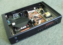
Attachments
Good evening Gents,
Thanks Bob, I'll definitely look at getting some heatsinks for the chips, also appreciate your warning of fake crowns! If anyone can recommend reliable genuine sources for these I'd be interested.
Anton, I had a look at the schematic - TDA pins 2 & 4 are tied so perhaps I'll try the non-A after fitting a (temporary) socket. I do intend getting the proper A version but it would be nice to prove the fault before purchasing. I will email the service manual to you shortly. My Alpha 5 has the CDM-9/44 mech, looks like your Plus has something different?
Regards,
Tyron
Thanks for the manual. Your player is definitely compatible with both a TDA1541 and a TDA1541A, having both a DEM oscillator cap and an SCK input. Testing with the spare TDA1541 you have would be useful.
The reference list of CDP/DAC/Mech I use indicated an Alpha 5 had a CDM-4, which was wrong, it has a CDM-9 as you say. The Alpha + uses a CDM-4/11. The Alpha + is really a Philips CD482 with a new case and DAC board, quite a common practice at the time, saved on R&D.
Be careful removing the old TDA1541A when installing the socket, in case it isn't at fault. Have you used desoldering braid before?
As for reliable sources for S1s and S2s, the only one I know of is well known members of this forum who occasionally sell them on the trading post section. eBay has a few, but hardly reliable. I guess you could take a calculated risk on a trader with a good history.
Good luck, at let me know how you get along.
Anton
It's been a while now but recently fitted a socket and plugged in the TDA1541 and success! ") So then got hold of a new/old stock TDA1541A which is in there now and very nice it sounds too!
So then got hold of a new/old stock TDA1541A which is in there now and very nice it sounds too!
Thanks for all the help and advice so far gents! Now does anyone have any suggestions for areas I could tweak and improve upon? Or should I maybe start a new thread I wonder?
I was thinking about renewing some of the caps and was wondering about some fancy Elna Silmics or similar to start with? I'm in no great rush though, happy to just listen and get used to the sound as it is now for a while.
Thanks again guys!
So then got hold of a new/old stock TDA1541A which is in there now and very nice it sounds too! Thanks for all the help and advice so far gents! Now does anyone have any suggestions for areas I could tweak and improve upon? Or should I maybe start a new thread I wonder?
I was thinking about renewing some of the caps and was wondering about some fancy Elna Silmics or similar to start with? I'm in no great rush though, happy to just listen and get used to the sound as it is now for a while.
Thanks again guys!
I'm glad to hear that you were successful. There is a massive amount of modifications that can be made to a player like this.
One critical piece of advice: do one mod, test it, don't do more than one mod between tests. That way if you have a loss of sound performance, or a loss of sound at all, you can back track and correct problems easily.
The first thing I would do is more a maintenance issue; replace all of the electrolytic capacitors. These only have a life of about 10yrs, and your CDP could be up to 15yrs old. When replacing them, you might as well improve them. I would recommend different brands/series for each function:
- Power supply: something with a low impedance, Nichicon ZL, Panasonic FC or FM, any of these will do. Some people like Sanyo OSCONs for decoupling the digital supplies.
- Signal path: its better not to use electrolytics for this application at all, but unfortunately with size and value constraints, they are your only option bar redesigning the analog output stage. Use Nichicon ES, Blackgate N, NH or NX, there are others to.
Try and stick close to the original capacitance values, and meet or exceed the original voltage ratings. It is fine to replace a cap with one of higher voltage rating, but beware that higher VR usually means larger size, and you want them to fit!
After that, the sky is the limit, you can:
- replace I/V and buffer opamps
- damp the chassis
- remove the SAA7220
- install a low jitter clock
- replace the whole I/V stage
- get an S1 or S2 for it
There are a huge amount of threads already on modding these first and second gen multibit players, I would check out those before starting another thread.
Don't hesitate to ask me whether mods you see done to other player are applicable to yours.
Anton
- Status
- This old topic is closed. If you want to reopen this topic, contact a moderator using the "Report Post" button.
- Home
- Source & Line
- Digital Source
- Arcam Alpha 5 - no output