After having assembled a few DACs, I am thinking to scratch build a 1541A DAC. While researching on the web, I found one implementation using a 317 CCS and an OP Amp as IV.
Is there any advantage using a CCS in place of a resistor? How is gain of the IV stage calculated with a CCS load?
Is there any advantage using a CCS in place of a resistor? How is gain of the IV stage calculated with a CCS load?
pftrvlr said:Say for example if 1541A output current ranges from 0 to 4mA, when a CCS is used, what is voltage swing we can expect?
Doesn't affect the voltage swing either, just offsets the 0 signal current so that the output of the transimpedance amplifier (I/V converter) can be dc coupled. The CCS set to -2mA results in the transimpedance amplifier seeing an input current range of -2mA to +2mA, but the magnitude of the current it sees at its input has not changed. (still 4mA) Voltage swing is determined solely by the feedback resistor employed in the I/V converter.
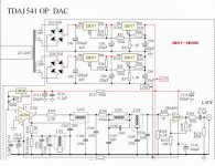
The CCS in this circuit is not used in the feedback resistor location, if you look carefully you will notice that it instead goes directly to the +15V rail.
The circuit design is rather unconventional, so I might have missed something else, but I suspect there might be a resistor omitted from the schematic between pins 2 and 6 of the 844 otherwise it is being used in a very unconventional fashion as perhaps a (close to) unity gain transimpedance amplifier with those odd connections to pin 5. I don't know and haven't the time at the moment to analyze further.
A ccs inside the feedback loop is not a real good idea for a variety of reasons not the least of which is if it works properly it should look like a very high impedance to any ac signal which should result in clipping at the output of the amplifier for any signal containing an ac component.
You're right, I mis-read the schematic. The CCS is not in the feedback loop.
I browse the AD844 info, it is specifically designed for current-voltage conversion. It does not use a feedback resistor in I/V application.
Haven't heard a lot about AD844. Wondering if it is good for hifi.
I browse the AD844 info, it is specifically designed for current-voltage conversion. It does not use a feedback resistor in I/V application.
Haven't heard a lot about AD844. Wondering if it is good for hifi.
pftrvlr said:You're right, I mis-read the schematic. The CCS is not in the feedback loop.
I browse the AD844 info, it is specifically designed for current-voltage conversion. It does not use a feedback resistor in I/V application.
Haven't heard a lot about AD844. Wondering if it is good for hifi.
I had a Sonic Frontiers dac 1 that used them and it most definitely used the standard I/V configuration with a resistor between pin 2 and pin 6. Look at p.9 of the AD844 data sheet for the standard configuration that shows this, and this even includes a table of recommended resistor values for I/V conversion.
Note that the dac I/V application shown on P.13 uses a dac that has an internal I/V resistor to assure good thermal tracking with the dac's internal ladder. Some older audio dacs have an internal I/V resistor but most new ones do not. (related to dac architecture issues)
Here: http://www.analog.com/static/imported-files/data_sheets/AD844.pdf
This a very old design, it has relatively good ac performance and what can only be characterized as mediocre dc performance by current standards.
They sounded ok, but would not be my first choice.. See all the threads here for recommendations of better op-amps. I like the National LM4562 family which is current sota. If you use dacs with differential current output take a look at the TI THS4131 differential amplifier - works great.
Thanks Kevin.
A quick search yields these two threads:
http://www.diyaudio.com/forums/showthread.php?s=&threadid=22206&highlight=ad844
http://www.diyaudio.com/forums/showthread.php?s=&threadid=16323&highlight=ad844
Looks like that AD844 can be used with TDA1541A without resistor between pin2 and pin6. And it was quite something 3 year ago in diyaudio.
The key is pin 5.. This is definitely not a recommended approach by the manufacturer of the chip, but it does apparently work.. Someone obviously spent some time figuring this out. Still the commercial applications I have seen using it as an I/V use the conventional transimpedance configuration - for audio I assume the theoretical loss of accuracy is an acceptable trade off for running it open loop. It probably sounds fine, I haven't tried it so I can't say. Seems easier than a fully discrete implementation which is what it emulates. Might be worth trying.
I'm not a fan of the TDA1541 so I don't follow those threads - I may have missed something.
Note that if a vendor decides to clone the AD844 under license down the road or Analog changes internal design details it is possible that this circuit may no longer work with newer chips. Just one of the risks of using a chip in ways not intended by the manufacturer and I've been burned this way... For DIY this probably does not matter.
FWIW this obviously will not work with most op-amps..
I'd say this is pretty clever and I will read the other threads to understand it better.
- Status
- This old topic is closed. If you want to reopen this topic, contact a moderator using the "Report Post" button.
- Home
- Source & Line
- Digital Source
- CCS Load for 1541A?