Actually, random noise + random noise = more noise. However, we also have more signal as well. Consider two current output DACs in parallel. The first DAC has an output currentOriginally posted by grataku
random noise + random noise= more noise or less noise?
I1 = Isig + Inoise1
and the second DAC output is
I2 = Isig + Inoise2
where all values are RMS.
When uncorrelated noise sources add, the resulting noise is
sqrt(Inoise1^2 + Inoise2^2)
If Inoise1 and Inoise2 have the same RMS value, then the total noise is
1.414*Inoise
so
Itotal = 2*Isig + 1.414*Inoise
Therefore, although the noise increased by a factor of 1.414, the signal increased by 2 so the SNR improved by a factor of 1.414.
Mike, that's exactly what I was saying. Noise adds but coherent signal adds more so the s/n increases, anyway in the interim I think I got your earlier post, although staggering would require a much more complicated circuitry than simple parallel.
What does quantization noise look like? Excuse my ignorance, but what happens if you send a signal to one dac, a signal 180 deg out of phase to another dac take the outputs from the two dacs and subtract them? Wouldn't that get rid of the quantization noise?
What does quantization noise look like? Excuse my ignorance, but what happens if you send a signal to one dac, a signal 180 deg out of phase to another dac take the outputs from the two dacs and subtract them? Wouldn't that get rid of the quantization noise?
"Quantization noise" is more accurately called "quantization error". Quantization error is actually introduced during the A/D conversion process - it is the difference between the quantized (digital) waveform and the analog input waveform. An ideal A/D converter basically "rounds" the analog input waveform to a finite set of discrete quantization levels - imagine rounding a real number (infinite precision) to an integer (finite precision).
If certain assumptions are made (mainly that the input signal is constantly changing and is not synchronous to the sampling rate) then the quantization error can be viewed as a uniformly distributed random number which can range from -0.5 LSB to +0.5 LSB (where LSB is the size of one quantization level of the ADC). Quantization error from sample to sample is uncorrelated (i.e., the quantization error at sample N is independent of the quantization error of all previous samples). Given these assumptions, the quantization noise looks like white noise with RMS level of LSB/sqrt(12).
Since quantization noise is introduced in the A/D conversion process, by the time it gets to the DAC it is actually part of the signal. Nothing can be done at the DAC end to eliminate it - at least not without affecting the signal as well.
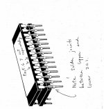
I decided to test "piggyback" two pairs of PCM1704K. I could only compare between a single and 2 in parallel (I'll do balanced later)
I believe my set-up is reasonably neutral and transparent.
I out from the DAC chip goes directly (20 cm of double shielded cable) to the +input stage transistors (2SC3722 and 2SA1455K) of the power amp (LC Audio Millenium run on batteries with 0.5F elyts and added MCap PP decoupling at every appropriate transistor (50uF on the legs of the power trans)).
The volume is controlled by low value resistors to ground and the -Input on the power amp, test volume load (DAC load) between 100 to 500 ohms.
The speakers are Dynaudio Contour modified using metallfilm resistors, CFAC coils and MIT MultiCap RTX.
I realize I have a somewhat different set up for the IV conversion and that this might play a role in my findings...
However in this set-up parallel dacs sound MUCH worse, upper midrange and high range completely looses transparency and precision and gets gritty and harsh.
Really not much more to say, it really sounds bad. The only thing that may have improved was upper bass or perhaps that was the only area my ears could stand, the level obviously increases.
There is no way I am going parallel.
I am pretty confused why others find it better
Forgot another piece of info that might explain my findings...as you probably figured there are no analog filtering except what is done by the poweramp and speakers, the power amp has a -3dB of 500kHz.
Prior to the dacs the signal is upsampled to 24/96 and then oversampled to 768kHz.
I run the dacs directly on a 24.576kHz clock.
Prior to the dacs the signal is upsampled to 24/96 and then oversampled to 768kHz.
I run the dacs directly on a 24.576kHz clock.
Originally posted by A 8
I realize I have a somewhat different set up for the IV conversion and that this might play a role in my findings...
Sounds are using a passive I-V converter - a 100 to 500 ohm resistor to ground? I think that you may get some strange interactions between the paralleled DACs in this case. Parallel DACs running into the summing node of an opamp-based I-V converter would be effectively isolated from each other.
"paralleled" DACs, as stated by Mike, can enhance s/n) by
3dB for every doubling of the number of converters.
(this concept is very appealing to Burr-Brown/TI and Analog Devices...)
However, unlike what some have said (including an
audio converter guy, Bob whats-his-name at ADI),
distortion is NOT reduced, in general. To reduce distortions
would require that the nonlinearity errors in the various
bits be random. In practice, any bunch of converters
you buy for this sort of project will likely be from the same
lot and thus be very likely to all have their errors skewed
in the same direction. Thus they'll be highly correlated.
On the other hand, buying the premium grade of any DAC
is a very good guarantee of getting better linearity and
hence lower distortion.
One common practice that seems guaranteed to mess up
the DAC's linearity is to use a resistor on the output of
a current-out DAC for the I/V conversion rather than an
op-amp summing junction. Saw some curves that a
friend did recently and the resistor version was pretty
pathetic.
Passive IV conversion
-Yes I am using passive conversion.
Right or wrong I found it to be sonically prefered.
Before settling for the passive variant I used the opa627 as I/V converter and my perception was that I actually had lower overall distorsion with the 627.
I lost on more subtle things like "body" and 3-D feel, "drive"
Particulary the interchannel time precison (not measured, just perception) was significantly better using passive conversion which convinced me to go passive as it really pulls you into whatever you listen to.
Michael
Hi; Quote....One common practice that seems guaranteed to mess up
the DAC's linearity is to use a resistor on the output of
a current-out DAC for the I/V conversion rather than an
op-amp summing junction. Saw some curves that a
friend did recently and the resistor version was pretty
pathetic.
I'm sorry but I would have to disagree with this. But it would also depend on which dac you were using I suppose. If you are using the AD1861 or 1862's by Analog Devices, then using a resistor for the I/V conversion is the only way to go(imho.. these dacs are the best you can get period, the 1862 being the better of the two). I used two dacs in a balanced config.(inverted data feeding the second one) feeding a bridged power amp direct and made the input R ... I beleive the value I used was a 562R, Caddock MK132....the load for the dac(i/v). To balance out the amp I used the same value on the inverting side. For volume adjustment I use a bit shift setup before the dacs. I say without a doubt that getting away from any opamps in the signal path is the best thing you could ever do to improve the sound. The amps are my own design( or should I say a compulation of designs and knowledge gathered over the past 20 some years).
And one other note, if you want to improve the sound of your equipment even more, get rid of those gawd awful electrolytic caps,all of them and replace them with polypropolene. In my power amps, which are basically bridged 200 watt modules, in the base amps I use a total of 800uF per rail..72 v rails and in the amps for the upper ends I use 600/rail... Solen 200uF/400v. Talk about clean and powerfull bottem end. I didn't know what good bottem end was until I made the swap.
WTS
Well, you may disagree, but them's the facts. You are correct
that some current-output DACs may behave differently than
others, but I've seen enough to say that in general, the linearity
(and hence distortion) will be significantly worse with a
resistor "I-to-V" converter.
You can debate whether it "sounds" better or not, but
the objective fact is that the DAC feeding the "zero" impedence of
transimpedance stage of suitable quality will have less distortion
than a DAC driving a resistor (and possibly some active
stage after that).
My experience has been that better objective
measurements have led to sound that was more pleasing
in the long term. There is valid debate as to which "objective"
measurements are best correlated to the audible experience,
but I've not seen and cases where consciously choosing
circuitry with less good performance has created long-term
satisfaction.
Hi BrianL;
Well those may be the facts, but there is a group of us in the city which I live and we all have a electronics background right from techs to profs and dean's of science's, as well as some members of the local symphony. Now you can have all the smarts in the world and do all the tests you can and want to say this should sound better than that, but it all comes down to how it sounds to your ears. As far as this change or implementation of the dac goes, we found without a doubt that it was by far more accurate to the ear than the conventional methods. Now none of us claim to have golden ears or anything, its just our findings.
Thanks.
And let me say that these listening tests were not done using second rate supporting equipment or done in one seating or in the same location.
- Status
- This old topic is closed. If you want to reopen this topic, contact a moderator using the "Report Post" button.
- Home
- Source & Line
- Digital Source
- Balanced or parallel DAC chips