I bought an unused TDA1541A off e-bay, and have built myself a simple dac. When I power up I get some strange readings, and hope to get some tips from more experienced diyers.
All power supplies work perfectly when not loaded. I use 78xx/79xx series regulators in a pretty regular fashion, but with snubber on outputs. When I connect the chip Vdd2 drops from -15VDC to -5.6VDC. I also get uneven dc offsets on the outputs, 4VDC on the right and 1VDC on the left.
Could there be an external factor in the cirquit causing this, or is it a faulty chip? Board looks clean with no short cirquits or other obvious mistakes.
Thanks for the quick reply.
I'll test the supply later this evening. Hope it's just a bad regulator.
Output offset from the dac was measured without the output connected. Will the I/V affect the measured offset on the dac?
I use a variation of rbroer's I/V-stage posted here on diyaudio. This one:
Having some problems with the I/V also. It seems to read 400mV offset on the output after the coupling caps when loaded. How's that even possible?
I'll test the supply later this evening. Hope it's just a bad regulator.
Output offset from the dac was measured without the output connected. Will the I/V affect the measured offset on the dac?
I use a variation of rbroer's I/V-stage posted here on diyaudio. This one:
An externally hosted image should be here but it was not working when we last tested it.
Having some problems with the I/V also. It seems to read 400mV offset on the output after the coupling caps when loaded.
How's that even possible?I bought an unused TDA1541A off e-bay, and have built myself a simple dac. When I power up I get some strange readings
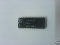
Could be a bad chip, what is the exact marking on the chip?
I had similar problems with TDA1541A chips with HSH0123 marking:
TDA1541A
11190
HSH0123
What happens when you disconnect pin 27 from VCC?
Well, I checked last night, and it's not the regulator.
Into 150R the dac gives 0VDC at Aor and 4VDC at Aol. I've measured around the whole circuit, and there are no short circuits or other obvious mistakes. The supply voltage still drops to -5.8VDC.
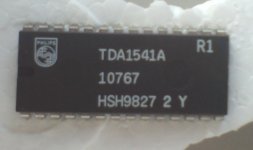
The marking on the chip is:
TDA1541A R1
10767
HSH9827 2 Y
What does it mean, by the way? Never took the time to try and understand the inscription.
I'll check voltages on all pins later tonight. And I can try to disconnect pin 27 to see what happens.
Thanks for the help everyone!
Into 150R the dac gives 0VDC at Aor and 4VDC at Aol. I've measured around the whole circuit, and there are no short circuits or other obvious mistakes. The supply voltage still drops to -5.8VDC.
The marking on the chip is:
TDA1541A R1
10767
HSH9827 2 Y
What does it mean, by the way? Never took the time to try and understand the inscription.
I'll check voltages on all pins later tonight. And I can try to disconnect pin 27 to see what happens.
Thanks for the help everyone!
Hi,
That '89 looks more authentic. Try measuring the resistance on the 'fake' chip between the power and gnd pins and you'll soon figure out why your power supply is getting upset ! I can't remember which supply it is but one of them only measures a few ohms on my fake.
Cheers,
Jon
That '89 looks more authentic. Try measuring the resistance on the 'fake' chip between the power and gnd pins and you'll soon figure out why your power supply is getting upset ! I can't remember which supply it is but one of them only measures a few ohms on my fake.
Cheers,
Jon
stoolpigeon said:Why would anyone bother to make a fake of the lowest grade (R1) version?
sp
Because someone erroneously claims that it is a "selected" grade and not jus a "relaxed specs" (=inferior) chip with lower linearity.
Cheers
Andrea
dantwomey said:When I was troubleshooting my TDA1541A DAC I used the table on this webpage to check all my TDA voltages. That should get you started.
I've checked voltages between all pins and ground
PIN _ Measured V __ "Correct V"
5_____ 0V ___________ 0V
6_____ 0V ___________ 0V
7_____ -2.8V ________ -3.5V
8_____ -0.9V ________ -3.9V
9_____ -3.5V ________ -3.9V
10____ -0.8V ________ -5.2V
11____ -4.6V ________ -5.5V
12____ -3.4V ________ -7.5V
13____ 0V __________ -7.4V
14____ 0V __________ 0V
28____ +4.97V _______ +5V
27____ +4.97V _______ +5V
26____ -4.98V _______ -5V
25____ -4.0V ________ 0V
24____ -3.56V _______ -3.5V
23____ 0V __________ -3.9V
22____ -4.0V _______ -3.9V
21____ -4.8V _______ -5.2V
20____ 0V __________ -5.5V
19____ -3.5V _______ -7.5V
18____ -1.0V _______ -7.5V
17____ -3.0V _______ -11V
16____ -0.27V _______ -11V
15____ -5.8V _______ -15V
So there's chaos all around. Doesn't make much sense to me at all. It's not the PSU, and I don't see how any external factors can cause this mess. The circuit is so simple, and I've double cheched it twice.
JonHarrison said:
Try measuring the resistance on the 'fake' chip between the power and gnd pins and you'll soon figure out why your power supply is getting upset ! I can't remember which supply it is but one of them only measures a few ohms on my fake.
Hmm. There's no low resistances between any of the supply pins and gnd.
Hmm. There's no low resistances between any of the supply pins and gnd.
Given that your -15V supply is 'wrong' the resistance between pins 5+15 and between 14+15 is high ?
Painkiller said:I bought an unused TDA1541A off e-bay, and have built myself a simple dac. When I power up I get some strange readings, and hope to get some tips from more experienced diyers.
All power supplies work perfectly when not loaded. I use 78xx/79xx series regulators in a pretty regular fashion, but with snubber on outputs. When I connect the chip Vdd2 drops from -15VDC to -5.6VDC. I also get uneven dc offsets on the outputs, 4VDC on the right and 1VDC on the left.
Could there be an external factor in the cirquit causing this, or is it a faulty chip? Board looks clean with no short cirquits or other obvious mistakes.
When I had a VERY similar situation it was lack of triggering to the TDA that caused my weird offset problems. I had the input to my 8414 shorted by putting the wrong capacitors in for C102 and C103. No output from the 8414. No input triggering to the TDA. Once that was corrected my TDA worked perfectly.
Regards,
Dan

An externally hosted image should be here but it was not working when we last tested it.
- Status
- This old topic is closed. If you want to reopen this topic, contact a moderator using the "Report Post" button.
- Home
- Source & Line
- Digital Source
- TDA1541A troubleshooting - faulty chip?