This was sent to me by a non member, he asked for me to post it for him and get comments on it.
On how much gain it has and whether it's a going concern for current output dacs as a discrete I/V and output stage?
Please don't shoot the messenger
Cheers George
On how much gain it has and whether it's a going concern for current output dacs as a discrete I/V and output stage?
Please don't shoot the messenger
Cheers George
Attachments
Hi, Cant figure out at all. If + and - are supplies, the output is at half supply (2k dividers). Or not ! Read on. If Gnd is ground then it does not do anything, the output sits at a voltage determined by supply pins.
Why does nobody seem to build anything these days, it's all just simulations with weird value components. Sorry, thats not meant as a critisism, just an observation generally") Oh and those 1K resistors will saturate each transistor putting a short on the supply. Something will go pop.
Oh and those 1K resistors will saturate each transistor putting a short on the supply. Something will go pop.
Regards Karl
Why does nobody seem to build anything these days, it's all just simulations with weird value components. Sorry, thats not meant as a critisism, just an observation generally
Oh and those 1K resistors will saturate each transistor putting a short on the supply. Something will go pop.Regards Karl
Hi!
As Mooly says, that one would not make you happy at all. Below you can see what i am using. This one is both simulated and built and i have used it for some years now and am very happy with it. Some of the component values are changed in the "real" ones but i can´t remember the exact values but i have around 15 volts and 10 mAmps in all transistors except Q3 and Q4.
Good Luck,
Anders
Attachments
I knew I have seen it before!
This is the LC-Audio MC preamplifier:
http://www.lcaudio.com/index.php?page=8
I think it could be used for I/V stage because of the very low input impedance and low noise. I have no idea about the gain (transconductance?). Perhaps someone having SPICE could be able to simulate it.
Laszlo
This is the LC-Audio MC preamplifier:
http://www.lcaudio.com/index.php?page=8
I think it could be used for I/V stage because of the very low input impedance and low noise. I have no idea about the gain (transconductance?). Perhaps someone having SPICE could be able to simulate it.
Laszlo
bappe said:Hi!
As Mooly says, that one would not make you happy at all. Below you can see what i am using. This one is both simulated and built and i have used it for some years now and am very happy with it. Some of the component values are changed in the "real" ones but i can´t remember the exact values but i have around 15 volts and 10 mAmps in all transistors except Q3 and Q4.
Good Luck,
Anders
Anders, have you noticed any issues with thermal stability (varying input DC offset or something) with this design? Also, have you ever had an opportunity to measure distortion? I imagine it would go down nicely if you changed R6 and R7 to CCS's. By TDA2134, I assume you mean OPA2134, and what kind of output buffer are you using? This gets what, about 1.25r input impedance?
cetoole, no thermal issues at all, variations over time has been in the 1-2mV range or less. I have tried this one with ccs as well but it sounds better without them and the dist figures are more than low enough the way i use it. I am not using any buffer for two reasons; #1 I think that 1k output impedance is low enough and #2 it sounds better without it! If it's not broken, don't fix it........
And yes, i do mean OPA2134.
BR,
Anders
And yes, i do mean OPA2134.
BR,
Anders
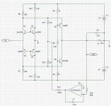
georgehifi said:This was sent to me by a non member, he asked for me to post it for him and get comments on it.
On how much gain it has and whether it's a going concern for current output dacs as a discrete I/V and output stage?
Please don't shoot the messenger
Cheers George
It should be noted that this circuit will only work with a floating power supply like say a 9V battery for example which would best be mounted to somewhat minimize capacitance to ground.. The value of those bias resistors is very critical, the values chosen are only suitable at extremely low supply voltages. DC stability of this circuit will be near non-existant as far as I can see.
I like Anders circuit much better and an thinking of something similar down the road for my dac. (Differential outputs)
- Status
- This old topic is closed. If you want to reopen this topic, contact a moderator using the "Report Post" button.
- Home
- Source & Line
- Digital Source
- Comments please on this I/V amp