So frustrated tonight, I bought a new Sanyo laser head so I started out replacing the laser that was playing fine the night before, the new laser can't read any CD at all. I checked the height of the turn atble and measure correct so I start adjusting the vr until it reads the toc but plays with shattered sound only, after spending hours still couldn't get it to play correctly. I put back the original laser but also failed to play, I think I messed up something but couldn't figure out yet, may be the ribbon cable turn bad....I don't know!
Can you check the eye pattern as Tibi described a few posts ago?
Does the sled move freely?
By the way, today the thinness I described yesterday was almost gone. That damn fresh solder...
I later replaced R48 and R49 with Dale CMF55. The initial result was some more clarity and more extension to top and bottom. Especially top. Let s see how this one goes... Tomorrow I ll do some more listening and then try the 100-300-100 pi-pad.

By the way, has anyone tried removing that metal ring on the spindle?
If we do not use a magnetic puck it probably just sits there rattling
I haven't but it seems like if it's removed it might just as easily create a cavity which could lead to vibrational resonances.
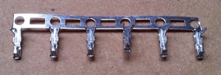
What is the name of this cable shoe, I have 4 too little.
Myself have 1 broken but I want order 20 pieces spare parts.
No good connection I must this soldering have no special tools for this.
And Yes, this connection breaks so easy
Too bad I had hoped that this cable was already made, plug in and play.
Ready mounted and tested
First, go try this connection then everything directly soldered on the PCB.
Regards,
Rudy
Attachments
Last edited:
What is the name of this cable shoe, I have 4 too little.
Those guys seem to be called crimps for pin headers...
I am using pretty much the same ones for another project. pin spacing probably is 2.54mm...
08-50-0114 Molex | Mouser
You can find the parts on Tibi's signature the Shigaclone BOM
I have found him:
SPH-002T-P0.5S - JST (JAPAN SOLDERLESS TERMINALS) - CONTACT, 0.05-0.22MM, CUT REEL | Farnell România
Regards,
Rudy
I have found him:
SPH-002T-P0.5S - JST (JAPAN SOLDERLESS TERMINALS) - CONTACT, 0.05-0.22MM, CUT REEL | Farnell România
Regards,
Rudy
Those guys seem to be called crimps for pin headers...
I am using pretty much the same ones for another project. pin spacing probably is 2.54mm...
08-50-0114 Molex | Mouser
They are 2.0mm pitch.
You can find the parts on Tibi's signature the Shigaclone BOM
I have found him:
SPH-002T-P0.5S - JST (JAPAN SOLDERLESS TERMINALS) - CONTACT, 0.05-0.22MM, CUT REEL | Farnell România
Regards,
Rudy
Hmmm, I can not order from Farnell because I have no company
Rudy
Hmmm, I can not order from Farnell because I have no company
Rudy
They sell to individual persons too. At least here in Latvia, I make order in Farnell home page and next day UPS postman is at my door, direct next day delivery from UK. Shipping is extra 5 euro.
By the way, has anyone tried removing that metal ring on the spindle?
If we do not use a magnetic puck it probably just sits there rattling
Just remove it.It add the mass to spindle.It is simply contact glued on the plastic.That part of the spindle is first that I removed in the beginning of nonmagnetic puck experimenting and the result was positive.
Cool. I will try it, although it does not seem glued, but rather held in place with those plastic clips. I tried to remove it on one of my bent spindles and the clips broke quite easily, so be careful cause we do not know what this breaking could do to the balance of the spindle.
Today I played a little with Tibi's puck. I wanted to reduce the metal ringing, so looking around the first thing that caught my eye was paper tape. I added two stripes on its bottom so that the tape comes between it and the CD. And then added some more on the top side.
The difference was quite substantial, although by trying with and without it, I kept wondering...
The change with the paper was that dynamics were quite more instant and violent. Bass and snare drums got the biggest influence.
However removing it again made the sound feel more 3d. Like bringing highs a bit out of phase making them feel like they fill the room.
To be honest I really like the attack power I got with the paper, but the sound seems a bit too... clinical...
Can you guys try this and give me your opinion?
Tomorrow I will try to get some teflon tape to try.
Tomorrow I will try to get some teflon tape to try.
I was going to suggest that, but you may have to score the tape to give it some "tooth" or the puck may not have enough friction to spin when the motor starts running.
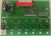
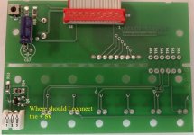
Where should I connect this + 5v, connecting to the display bottom.
Connect the + 5v to: 1 2 or 3 to the display?
Regards,
Rudy
No one can help me with this question?
If I connect this +5v wrong I have a problem, I would like to know for sure.
Regards,
Rudy
Attachments
Last edited:
Rudy,
Based on your attachments +5V is going to 1.
You can always check schematic at vicol audio : shiga CD transport for clarification.
Regards,
Tibi
Based on your attachments +5V is going to 1.
You can always check schematic at vicol audio : shiga CD transport for clarification.
Regards,
Tibi

- Home
- Source & Line
- Digital Source
- Finally, an affordable CD Transport: the Shigaclone story