tonyptony,
I´m going to send you parts for one remote and include R52 as well.
Regards,
Tibi
Thanks Tibi! Hopefully I won't fry that tiny little resistor!
 I'll have to practice some more on some scrap PCBs I have.
Here's a picture of the pin connector Tibi supplied with the kit. Is it best to use stranded or solid wire for this? Does the wire get inserted past the large tabs only, or the large tabs and the smaller ones in the middle, before crimping? What's a good tool to use for a reliable crimp? (assume I don't have the actual tool made for this sort of thing - the actual crimp tool costs over 270 Pounds!)
Attachments
![3617210-40[1].jpg](/community/data/attachments/311/311961-040ca272b461a54bc52917fe847d61f9.jpg)
Wiring of 6 pin abd 3 pin cables
When wiring these up, do I keep the connectors in the same orientation when wiring across from the pin of one connector to the other, or is one connector flipped over? I hope I'm being clear. If I expect to run the wires all in parallel from one connector to the other, do I orient the connectors back to back with the same side (of each) facing up, or one of them flipped?
Never mind. I see woodturner_fran answered this a little while ago. The connectors orient back to back with the same side facing up.
Last edited:
No voltages at V1-V4?
Can I check anything on the PCB with just the +8V connector inserted, before I plug in any other cables?
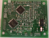
D@mn it! D@mn it! D@amn it! Since I was looking at the upper side of the board I mistook the location of the "+8V" on the PCB as denoting the location of the actual positive side of the voltage rail. I didn't even see the "J6" label on the PCB. I realized that is the alternate method of also identifying Pin 1, but only when it was too late. So for a short time (~10 seconds?) I had the voltage feeding the PCB reversed!
Once I powered down and reversed things the board and display seem to have come on okay. I measure +4.94 VDC at all four testpoints. But I have the bad feeling I probably damaged something. I caught the slightest hint of burning something just before I pulled the power. If anyone can tell me what would happen when this PCB is fed with reversed voltage I'd like to know - but I suspect I won't be happy the hear it.
Can I check anything on the PCB with just the +8V connector inserted, before I plug in any other cables?
D@mn it! D@mn it! D@amn it!
Since I was looking at the upper side of the board I mistook the location of the "+8V" on the PCB as denoting the location of the actual positive side of the voltage rail. I didn't even see the "J6" label on the PCB. I realized that is the alternate method of also identifying Pin 1, but only when it was too late. So for a short time (~10 seconds?) I had the voltage feeding the PCB reversed!Once I powered down and reversed things the board and display seem to have come on okay. I measure +4.94 VDC at all four testpoints. But I have the bad feeling I probably damaged something. I caught the slightest hint of burning something just before I pulled the power. If anyone can tell me what would happen when this PCB is fed with reversed voltage I'd like to know - but I suspect I won't be happy the hear it.
Last edited:
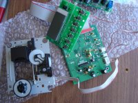
Well, I'm not quite sure what to make of this. I finished making all the cables and started checking things one by one after plugging in each cable. The PCB test points seem okay. I powered down and then plugged in the three pin cable for the front panel. The display seems to do what it's supposed to do. Then powered down again and plugged in the 6 pin motor drive cable. As soon as I powered back up the mechanics of the sled started slamming against the stop closest to the hub. I pulled the power immediately.
The sled has had its shorting blob removed and the laser cover is off.
I made that cable by laying out the six wires in parallel, between the connectors which were back to back, both showing their guide bars pointing up.
The sled has had its shorting blob removed and the laser cover is off.
I made that cable by laying out the six wires in parallel, between the connectors which were back to back, both showing their guide bars pointing up.
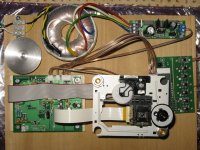
I'm attaching a photo of the setup. Right now I have it built on a slab of hardboard so I can get it up and running quickly for testing and evaluation.
If you expand the image to full size you can see that on both ends of the 6 pin cable, at the connectors, I circled the same wire at each end so you can see the orientation. It's a black circle in each case so it may be a little hard to see.
If you expand the image to full size you can see that on both ends of the 6 pin cable, at the connectors, I circled the same wire at each end so you can see the orientation. It's a black circle in each case so it may be a little hard to see.
Attachments
Yes, yours is wired the reverse of mine, Fred. I wish someone would have corrected w_f's direction in that range of posts. Could I have now damaged anything?
Does that also mean the three pin CD Door cable needs to be wired in this same reverse orientation?
Tibi, please update the documentation to show the correct orientation of the connectors for wiring, and also add a warning about which pin is the positive side of the 8 VDC when looking at the top of the PCB.
Fred, dimkasta, and Eric, thank you all for the correction. I rewired the 6-pin and the 3-pin and finally got things to work. 
As to how well things work, that will be the test. I'm still not sure all this miswiring hasn't damaged anything. I haven't yet installed the output BNC so I'm not sure what is coming out. What I do notice is that when I tried moving from track to track on my first test CD, with moves to some of the tracks the mechanism sounded like it wanted to grind coffee. In those cases it took up to several seconds for things to quiet down and run normally. I checked the height of the CD tray on this mechanism and it's 19.61 mm. I thought that was close enough to the desired 19.58 mm so that it wouldn't hunt around so much. It's either more sensitive than I thought, or maybe something is wrong.
As to how well things work, that will be the test. I'm still not sure all this miswiring hasn't damaged anything. I haven't yet installed the output BNC so I'm not sure what is coming out. What I do notice is that when I tried moving from track to track on my first test CD, with moves to some of the tracks the mechanism sounded like it wanted to grind coffee. In those cases it took up to several seconds for things to quiet down and run normally. I checked the height of the CD tray on this mechanism and it's 19.61 mm. I thought that was close enough to the desired 19.58 mm so that it wouldn't hunt around so much. It's either more sensitive than I thought, or maybe something is wrong.
I wired up an old Tiffany RCA jack to the digital out for testing purposes. After carefully checking for shorts etc I took the chance and hooked the transport up to my DAC. I was gratified to hear music coming from my system.  But, some observations having to do with track hunting and dropouts.
As I was listening to some of my own CD-Rs (all of my own discs are done on T-Y blank CDs using a Plextor Premium writer), I was not happy to see that as I went from track to track there was a lot of hunting before the sled settled down and started playing - in most cases. In some cases the hunting would not stop until I jumped back and forth across tracks. And sometimes when it finally did start playing a track there would be several seconds of audible dropouts before the music would play smoothly. These are CDs which have been brought to audio shows and played successfully on any number of transports and players. Commercial CDs appear to play okay, but even these sometimes exhibit track hunting when I jump to other tracks.
What mght this suggest?
As to the sound itself... I don't want to say too quickly. This thing is brand new and should have a lot of time put on it before I start comparing it to my reference. But it shows promise.
But, some observations having to do with track hunting and dropouts.As I was listening to some of my own CD-Rs (all of my own discs are done on T-Y blank CDs using a Plextor Premium writer), I was not happy to see that as I went from track to track there was a lot of hunting before the sled settled down and started playing - in most cases. In some cases the hunting would not stop until I jumped back and forth across tracks. And sometimes when it finally did start playing a track there would be several seconds of audible dropouts before the music would play smoothly. These are CDs which have been brought to audio shows and played successfully on any number of transports and players. Commercial CDs appear to play okay, but even these sometimes exhibit track hunting when I jump to other tracks.
What mght this suggest?
As to the sound itself... I don't want to say too quickly. This thing is brand new and should have a lot of time put on it before I start comparing it to my reference. But it shows promise.
Rudy, look at Tibi's instructions for Shiga assembly (the PDF file found on his website). He recommends a heatsink which you should be able to get from Farnell. I think it has an adhesive thermal layer, so it will stick to the chip. No mounting hardware should be needed.
- Home
- Source & Line
- Digital Source
- Finally, an affordable CD Transport: the Shigaclone story