Nice. I'm still wondering, though, about using metal screws and creating multiple ground points through the frame.
I was thinking of using a steel or nylon washer below the frame with a coil spring on the washer to create a "floating" transport. Washer and nut on top to hold things down, but in effect not hard mounted. Spring stiffness can be adjusted with the nut to perhaps tweak the sound.
Didn't some of the higher end transports use floating or bushing mounted mechanisms?
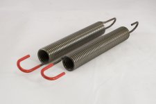
If you use mechanism with integrated PCB it is simple to apply floating design ,just make the wings say 10cm coming from four perforations on steel mechanism plate where usually standoffs are screwed.Than you can do four standoffs which can be used to attack the spring like that on picture and than you can suspend the mechanism on bottom of the spring and test with added lead weights on the extremity of the wings till the mechanism get stable when spinning and test with more or less mass to your liking.Here is my TT mass loaded springs example.
Attachments
That is a wonderful idea, I was contemplating doing this sort of comparison myself when I was doing my big capacitor tests. Clocks and oscillators are among the most contended Shiga components - there is little agreement at all (which is why I hesitate to include the subject in my Shigaclone guide).
If you would accept a suggestion from me, consider conducting your tests with all clocks powered from identical PSUs (or PSUs based on the same topology where differing clock requirements preclude using the exact same PSU). I think it is safe to assume that the clock's PSU will affect the resulting sound, which in turn could result in skewed or downright false conclusions regarding the performance of the clocks themselves.
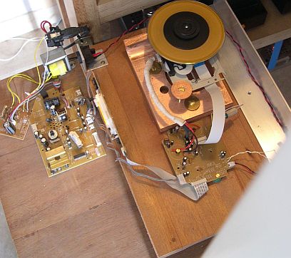
Hi alphaigor, I love how focused and radical your approach is. Your rig reminds me of nemo1968's hand-built Shiga mech:
http://www.diyaudio.com/forums/digital-source/120229-finally-affordable-cd-transport-shigaclone-story-94.html#post2543016. I wonder if you have seen it?
In my experience brass is the best (or copper or bronze, if you can get them). These three are the best "vibration conductors", which is the most important factor when mounting the mech rigidly. Grounding is irrelevant, as the mech frame is not connected to any electrical circuit (and if there are any spurious induced currents, it is certainly better to dissipate them over a large conductor, than try to contain them in a small frame).
uncle_leon ,
In fact nemo1968 is myself.I couldn't log in one day so I made new account and was obligated to use different name since nemo was lost somewhere under the virtual sea surface
") and still exist somewhere.This is the updated version of that same Nautilus ,it even uses 150Ah lead-gell battery as fuel like Nautilus did in Verne book with exception that the Nautilus battery was sodium/mercury.I am glad that you like it.
and still exist somewhere.This is the updated version of that same Nautilus ,it even uses 150Ah lead-gell battery as fuel like Nautilus did in Verne book with exception that the Nautilus battery was sodium/mercury.I am glad that you like it.Interesting approach to slow down the sled.
It would be an interesting experiment. When I receive the new mechanics I will try it.
Perhaps we could also slow it gradually down by attenuating the motor signal in steps to better see any bennefits? Perhaps with a series/shunt 10k trimmer? This might also allow for a better track skipping time.
By the way I completely understand what you mean that digital pushes us to skip tracks while vinyl pushes us to listen to at least entire songs...
If you use mechanism with integrated PCB it is simple to apply floating design ,just make the wings say 10cm coming from four perforations on steel mechanism plate where usually standoffs are screwed.Than you can do four standoffs which can be used to attack the spring like that on picture and than you can suspend the mechanism on bottom of the spring and test with added lead weights on the extremity of the wings till the mechanism get stable when spinning and test with more or less mass to your liking.Here is my TT mass loaded springs example.
Wow. You sir, are on the edge! Of what, I don't know. Seriously, that's very impressive

I was actually thinking of doing this in the opposite direction. Imagine these standoffs mounted to the bottom plate of the enclosure. The male threaded part then has a flat washer on it followed by a spring. The spring is of wide enough diameter that the transport frame can rest right on them when the ends of the standoffs are through the holes in the TT frame. Then a washer and nut on the top of the standoff.
Mounting the TT rigidly on to even two standoffs follows the philosophy of transferring vibration into a high mass target. Spring mounting assumes the philosophy of damping the vibration through lossy material. I wonder which one will work better? Easy enough to try both.
Attachments
dimkasta,Interesting approach to slow down the sled.
It would be an interesting experiment. When I receive the new mechanics I will try it.
Perhaps we could also slow it gradually down by attenuating the motor signal in steps to better see any bennefits? Perhaps with a series/shunt 10k trimmer? This might also allow for a better track skipping time.
By the way I completely understand what you mean that digital pushes us to skip tracks while vinyl pushes us to listen to at least entire songs...
I see we are speaking the same black language
 .Digital is good when possibly not so digital.Before I settled on silicon thread solution I realized that adding a series resistance to motor resulted in more human sound.The only problem was that the chip was slightly hotter than usual so I took a mechanical RPM reduction route solution and it worked.Shunting I haven't tried because I was afraid to eventually burn the chip and since series connection gave result that was proof that something can be done different way.
You really need to post some better photos or a vid
By the way, which is the chip that was running hot? The bridge?
Perhaps we could help it with a simple npn buffer?
Anyway, I m a bit suspicious of how the slowing down could affect the reading workflow... The x1 speed and the analogue analogy sounds nice, but it could just be that the mechanism never gets the chance to correct errors and the chip or the dac just fills in the blanks...
Wow. You sir, are on the edge! Of what, I don't know. Seriously, that's very impressive
I was actually thinking of doing this in the opposite direction. Imagine these standoffs mounted to the bottom plate of the enclosure. The male threaded part then has a flat washer on it followed by a spring. The spring is of wide enough diameter that the transport frame can rest right on them when the ends of the standoffs are through the holes in the TT frame. Then a washer and nut on the top of the standoff.
Mounting the TT rigidly on to even two standoffs follows the philosophy of transferring vibration into a high mass target. Spring mounting assumes the philosophy of damping the vibration through lossy material. I wonder which one will work better? Easy enough to try both.
Yes ,that is right.You can test both approaches that way and you will be the judge of the result.If you like both solutions sound you can try hanged springs with mass concentrated on the point where spring is connected to mechanism.Lead weights if thick enough are excellent for combining hard standoff solution and soft one because of mass concentration on energy transfer point and thanks to springs there is less feedback from outside which is good for laser.
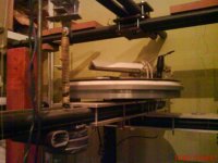
Maybe my TT solution is extreme but it works for me.TT springs from the photo are not just connected to chassis and sub chassis they are decoupled from them with spikes so the spring don't upset anything when activated because spikes prevent springs to move in spiral direction clockwise and anticlockwise endlessly and that way the resonance of the spring is very low almost zero hertz so we arrive close to hard platform solution but without feedback problem.Imagine that this TT use air tangential arm which is mission impossible for soft suspended tables.Arm see this sub chassis as solid one thanks to spikes stabilizers which prevent horizontal play when vertical movement occur.
You really need to post some better photos or a vid
By the way, which is the chip that was running hot? The bridge?
Perhaps we could help it with a simple npn buffer?
Anyway, I m a bit suspicious of how the slowing down could affect the reading workflow... The x1 speed and the analogue analogy sounds nice, but it could just be that the mechanism never gets the chance to correct errors and the chip or the dac just fills in the blanks...
I will try to find some better photo device.The chip equipped with heat sink feels hotter with series resistor.
Maybe that is right in theory but my practical experiment gave me more details in reproduction and more effortless sound.When you look in mechanism gears you will see that the movements are so fast that is impossible that laser is not stressed with that aggressive motion.When I softened the motion by resistor ,gears were moved more gently and the laser became much quieter which led me to conclusion that laser have less mechanical correction to do otherwise would simply start to skip if not driven fast enough by sled motor.With silicon thread I am not able to hear laser noise anymore and I hear details that I usually hear on LP record which I didn't heard on CD disc of equivalent material.Maybe my solution is questionable but the music heard through this approach is right in every way.The sound is not boring like with some 10000eur ,washed out players with advanced error correction ,but opposite.I think that there are no blanks inserted.
cool
Do you remember the value of the resistor?
Thinking about it now, shouldn't a series resistor make it an easier load?
Also, have you tried adding a ceramic cap on the motor (0,1uF or something)? This should make it even more quite and further prevent noise spikes
An interesting article that agrees with your cabling observations is here
Pololu - 9. Dealing with Motor Noise
cool
Do you remember the value of the resistor?
Thinking about it now, shouldn't a series resistor make it an easier load?
Also, have you tried adding a ceramic cap on the motor (0,1uF or something)? This should make it even more quite and further prevent noise spikes
An interesting article that agrees with your cabling observations is here
Pololu - 9. Dealing with Motor Noise
If I remember well it was value about 30-50ohm but don't take my word ,start with 10ohm for example and than see what happens.I didn't tried cap.I thought the same about loud but the result was opposite.Maybe the chip did have to do more polarity alternations because the motor reacted slower for chip but enough fast for laser needs,I have no idea.The fact is that the heat sink turned normal when I removed resistor.It is not big problem if you piggyback solder some copper foil on heat sink to increase efficiency.I only know that now when the motor have constant rotation in one direction the chip is nearly cold and not slightly warm like before without the resistor on motor.
If I remember well it was value about 30-50ohm but don't take my word ,start with 10ohm for example and than see what happens.I didn't tried cap.I thought the same about loud but the result was opposite.Maybe the chip did have to do more polarity alternations because the motor reacted slower for chip but enough fast for laser needs,I have no idea.The fact is that the heat sink turned normal when I removed resistor.It is not big problem if you piggyback solder some copper foil on heat sink to increase efficiency.I only know that now when the motor have constant rotation in one direction the chip is nearly cold and not slightly warm like before without the resistor on motor.
I wonder if you could have the best of both worlds by installing some sort of gearbox (slow gear for playback, fast gear for seek). Perhaps a clockmaker would be able to suggest a solution.
Either way, I would also love to see more and better pictures of your rig, and a film would be perfect
@dimkasta - great link, thanks!
Today I made a couple of basic modifications to the Mini PiTbull.
First I removed the two smd I slightly bend the heatsink keeping the pressure on the plate not the chip and then cut it away instead of desoldering I find that somehow a better solution.
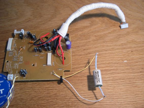
I installed an E5 using Oscon and made some prep for experimenting with the (in)famous C06.....dropped a wondercap in.....wiring is Mundorf Silver/Gold
First I will ditch the horrible puck and spindle its deviation is exactly in line with what you paid for 5 dollar the laser struggle is sometimes hilarious.
Anyway the contraption is spinning and besides some toc issues okay enough.
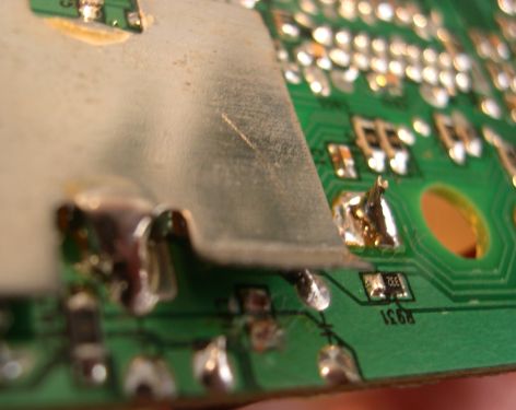
First I removed the two smd I slightly bend the heatsink keeping the pressure on the plate not the chip and then cut it away instead of desoldering I find that somehow a better solution.
I installed an E5 using Oscon and made some prep for experimenting with the (in)famous C06.....dropped a wondercap in.....wiring is Mundorf Silver/Gold
First I will ditch the horrible puck and spindle its deviation is exactly in line with what you paid for 5 dollar
the laser struggle is sometimes hilarious.Anyway the contraption is spinning and besides some toc issues okay enough.
I wonder if you could have the best of both worlds by installing some sort of gearbox (slow gear for playback, fast gear for seek). Perhaps a clockmaker would be able to suggest a solution.
Either way, I would also love to see more and better pictures of your rig, and a film would be perfect
@dimkasta - great link, thanks!
Thanks for suggesting the idea.In fact I was thinking about two speed gear but I realized that I don't need remote after 4 mounts of using that version of transport without any more modification.Usually ,during past years I made modifications on daily basis and I was sick of trying to materialize the sound that I imagined.I have destroyed old version and 5 months ago I started new one.It took me over month of thinking and constructing an finally after long years I forget the remote.It is nice feeling.The music is hallucinogen now and that is the point of the story.You fall asleep when starts and wake up when it is finished.If I need certain track during testing I do it manually or press the skipp button while I working on my speaker cable .For a 2m speaker pair cable construction I spend around 130 hours of time so 130 seconds of waiting isn't problem at all
.Thanks to this transport I recently constructed new series of signal wires which works exceptional in systems costing from 3000 to 30000eur.The comments of my customers regarding cables are that the timing of the music is fabolous with body and details not covered with mid band presence.That is how I experiencing the sound of the transport and I would hardly developed the cables of such quality if I was using say Ac*****se player costing 150x more which is soulless machine from my point of view and worst of all it have totally wrong timing of the music ,it's boring ,you really fall asleep with it but you don't want to wake up anymore for two reasons ,because sounds bad and because you want to shut yourself after spending 9000eur on useless peace of metal so better fall asleep and forget for awhile.I must borrow camera from a friend and will try to publish video to show you the machine in action.
Last edited:
Hi Nemo,
You know I use wire with weight on the gear train.
What would you say would be a "safe" amount of grams (approx) to use...
I have no idea how harmfull it can be to lets say use 10 grams instead of 1 gram.
I really like the one direction motor idea....I never search for tracks unless a friend with cds comes over....
I am putting the caps on the motor soon
The term "soulness" is very well choosen for the other transports once our contraption is in play
Hi Nemo,
You know I use wire with weight on the gear train.
What would you say would be a "safe" amount of grams (approx) to use...
I have no idea how harmfull it can be to lets say use 10 grams instead of 1 gram.
I really like the one direction motor idea....I never search for tracks unless a friend with cds comes over....
I am putting the caps on the motor soon
The term "soulness" is very well choosen for the other transports once our contraption is in play
Erik,
I didn't tried more than few grams.I always checked that chip with heat sink and it was OK regarding temperature.I stoped with these few grams because I saw that the gear clearance was lessened to extent to calm much more the confused motor motion.When I applied much more force by hand the skipping occurred so the conclusion was that it is important to find the middle value.I didn't experiment further because after that I passed on air bearing laser guide and the mass loaded thread solution was removed by slight inclination of the air bearing that hold the disc spin motor.I inverted the concept so the gravity regulated with inclination did the thread job.My conclusion was that is more important finding golden ratio of applied gravity rather than insist on maximal because sound developed was too heavy ,it was correct but too heavy to full enjoy it ,at least for me.That would be maybe topic about tastes but since we are DIY-ers the end result depend only to our own hearing needs what is great.If audio would be only objective that would be tough task for my ears ,I wouldn't listen to the music except live events if i could not personalize the sound system.I went with mass of 30 gram applied on air bearing and have found out that the slight inclination is sounding better.The resulting balance of overall sound was correct.The lesson for me is that that CD game is adjustement of different resonances in the cd system ,all together ,rather than obligatory kill some of them immediately ,it is energy flow that together give certain result ,as in every other component in the system ,like TT device for example or human interaction synergy after all and there is no ready recipe how to make it since result is mostly ear visible ;at first 7g and 3g seems pretty the same but the consequences may be very different. Sorry ,but I moved to fast with that project so I can't give you any certain answer regarding original mechanism and I have bad habit not to document my findings but on the other side this is good because person don't imprison himself by some drawings and data.Experiment can only tell you.I only know that the laser sled friction is the significant enemy of the cd sound so I went to frictionless air bearing.The sound of cd is very obvious to mechanical feel of various components involved in this job.If movement is smooth the sound is alike.If movement is stressed by friction the listening is more stressful too.This can be heard on laser noise ,the less you hear from it the better it is in my experience. That's the proof that laser behave more like walk in the park instead of running like hunting dog in the woods.Cd design seems easy ,like many people believe about 1/0 unimportance and think that is only needed any 75ohm cable to do the job.They don't realize that the voltage is carrying the 1/0 information which is lately decoded in other place and the cable must be as good as possible like every other signal cable in the audio chain.It carries many mHz over it attached to voltage so resonance control must be applied there too.This is the only one of many variables in the cd guess chain.
Yes the skip function is useful for evaluation and otherwise not desired very much if you chose right material
 .
.Let us informed on capacitor mod results ,I am curious.
Beside soulless I would add term boneless too as many other more and unless we didn't discovered this beauty thanks to Peter generous share I never needed to find these words since all players sounded more or less the same
.We don't develop only the music perception but our vocabulary too ,we are blessed persons in many ways.I m really curious about the motor cap too...
I ve been seeing them in all motors everywhere... from small RC cars to whatever I could think of. Not seeing one here was really weird.
The nice thing is that the motor PCB makes it really easy to mount a ceramic bead right on the motor terminals
I ve been seeing them in all motors everywhere... from small RC cars to whatever I could think of. Not seeing one here was really weird.
The nice thing is that the motor PCB makes it really easy to mount a ceramic bead right on the motor terminals
Typically you will want to use anywhere from one to three 0.1 µF ceramic capacitors soldered as close to the motor casing as possible.
For greater noise suppression, you can solder two capacitors to your motor, one from each motor terminal to the motor case as shown in the picture to the right.
For the greatest noise suppression, you can solder in all three capacitors: one across the terminals and one from each terminal to the motor case.
- Home
- Source & Line
- Digital Source
- Finally, an affordable CD Transport: the Shigaclone story