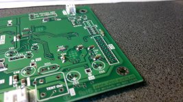
is this attenuator suitable for use with shiga? Microwave Coaxial Attenuator BNC 1GHz 10dB Variations 1nu ll3 dB6 dB20 | eBay
and how much attenuation is needed ?
and how much attenuation is needed ?
Can't get to this from work. How much attenuation is needed (in dB)?
Shiga output level is ~ 2V you need ~0.5V to be in S/PDIf specs:
Physical connection: Cable: 75ohm +/-5% (l<10m) or 75ohm +/-35% (l>10m) Line driver: Zout: 75ohm +/-20% (100kHz .. 6Mhz) Vout: 0.4Vpp .. 0.6Vpp, <0.05Vdc (75ohm terminated) Line receiver: Zin: 75ohm +/-5% Vin: 0.2Vpp .. 0.6Vpp
Cable: 75ohm +/-5% (l<10m) or 75ohm +/-35% (l>10m)
Line driver: Zout: 75ohm +/-20% (100kHz .. 6Mhz) Vout: 0.4Vpp .. 0.6Vpp, <0.05Vdc (75ohm terminated)
This can be achieved using a resistor divider (included in new Shiga board) or by an external attenuator with 12dB attenuation.
Regards,
Tibi
Some time ago, in a TI application note I found an article who treated piezoelectric effect in ceramics SMD capacitors.
The article concluded that the mounting of current SMD components is not optimal and in order to minimise this effect all ceramics should be placed on the edge side.
I decided to make a test and see if this will bring any sonic difference.")
Regards,
Tibi
The article concluded that the mounting of current SMD components is not optimal and in order to minimise this effect all ceramics should be placed on the edge side.
I decided to make a test and see if this will bring any sonic difference.
Regards,
Tibi
Attachments
Shiga output level is ~ 2V you need ~0.5V to be in S/PDIf specs:...
This can be achieved using a resistor divider (included in new Shiga board) or by an external attenuator with 12dB attenuation.
Regards,
Tibi
Thanks Tibi. I did get a chance last night to look over uncle_leon's info in his posted link:
Tony, the main reason we are tinkering with L-pads and Pi-pads is that signal produced by Shiga is too high and needs to be attenuated in order to meet the S/PDIF specification. See the output resistors section in my guide.
Hi Tony, I recommend a 75-Ohm Pi-pad, which requires one 125R resistor and two 140R resistors. All of these are available from me, in both the cheaper and the "extreme" variety.
uncle_leon, I appreciate the detail in your link. I guess what concerns me is that your recommended 125R/140R Pi-pad solution yields a circuit with a 77.5 Ohm characteristic impedance and a return loss of only 35.5 dB. IME that's enough to cause some distortion of the signal along the line. Your link indicates the ideal combination will be 139.9R/125.3R, which would yield a return loss of 114.6 dB with the desired attenuation (significantly better of course). Can you provide custom resistors which meet these needed values?
You can manually move the CD Sled by turning the gear drive to the point that the tab contacts the switch and closes it. Assuming the switch closes, you can test for continuity through the cable and all the way to the processor board.
From what I see in your movie, the laser is not powered and from what I see in your pictures the 16pin flat cable is not fully inserted in connectors. Please check again.
Sean, Tibi thanks a lot..
finally i solved the problem;
when i was making 6 pin cable i had made the cable pins in reverse order.. corrected and its running now but i have same cd turntable height problem you mentioned before.. im pulling it to upward and its moving about 0.5 mm..
Sean,
where did you apply the glue, under the turntable where meets the shaft?
thanks..
endia,
Once I fine tune the exact height for the CD Turntable, I apply some tape to the shaft to form a "stop" or "step" so the CD Turntable cannot move down the shaft.
In my case, the CD Turntable is tight enough on the shaft so that it will not likely slip or spin relative to the motor shaft as the motor ramps up to speed, but if it ever does start to spin, you can pull the CD Turntable off the shaft, a dab of water based adhesive, such as "Elmers" to the shaft and CD Turntable hole and slide it back to the "stop" you made with the tap. That way, if you ever needed to remove the CD Turntable in the future, with some effort you can remove the CD Turntable.
The more permanent fix is superglue. With this, once you have the CD Turntable exactly where you want it, apply the super glue it to the top of the CD Turntable where the shaft is visible and it will wick down the shaft enough to secure the CD Turntable in place....or you can do that from the bottom if you want.
Tibi,
So the Shiga "built and tested" versions have the needed 12 db attenuation, or 0.5V output for direct S/PDIF connection to a DAC...no need for additional attenuation?
Reason I ask is I have 10db and 15db Mini-Circuit 75 ohm attenuators on order.
Is it "better" to use the 10db or 15db Mini-Circuit 75 ohm attenuators versus the voltage divider?
IF you are in agreement that the Mini-Circuit 75 ohm attenuators are one of the preferred methods...then the voltage divider resistors would need to be removed and a jumper added. Which resistors are these on the board and which one(s) need to to be jumpered if removed?
That leads to the next question...do you have a complete circuit diagram of the new Shiga processor board available?
"This can be achieved using a resistor divider (included in new Shiga board) or by an external attenuator with 12dB attenuation."
Tibi,
So the Shiga "built and tested" versions have the needed 12 db attenuation, or 0.5V output for direct S/PDIF connection to a DAC...no need for additional attenuation?
Reason I ask is I have 10db and 15db Mini-Circuit 75 ohm attenuators on order.
Is it "better" to use the 10db or 15db Mini-Circuit 75 ohm attenuators versus the voltage divider?
IF you are in agreement that the Mini-Circuit 75 ohm attenuators are one of the preferred methods...then the voltage divider resistors would need to be removed and a jumper added. Which resistors are these on the board and which one(s) need to to be jumpered if removed?
That leads to the next question...do you have a complete circuit diagram of the new Shiga processor board available?
"This can be achieved using a resistor divider (included in new Shiga board) or by an external attenuator with 12dB attenuation."
Hi Sean,
New Shiga "built and tested" do not need and external attenuator or attenuation.
Needed attenuation is provided by R48 and R49.
IMHO voltage divider is a simple and clean solution.
A better solution is to use a very high quality s/pdif transformer with 12dB attenuation, not a 75ohm attenuator.
Commercially attenuators are resistive or with galvanic isolation, case that there must be a transformer inside. The problem si that such transformer attenuators are high bandwidth, made for TV or computer-LAN applications, ranging from few MHz to GHz. What we need here is a attenuator for s/pdif bandwidth. So for a sampling of 44.1KHz (normal CD) you have a corresponding bitrate of 2.8MHz and exactly in this range the great majority of transformer attenuators will fail.
If you want to remove the resistors there are R48 and R49. Take the signal from R48.
All new SHiga documentation is available at vicol audio : shiga CD transport

Regards,
Tibi
Last edited by a moderator:
I got one more complain about CD puck wobbling, therefore I have contacted the turner and I´ll go this week-end to discuss this with him.
It is also my fault that I have not tested entire batch.
In the meantime, if you encounter wobbling problem with your puck, please let me know and I´ll send you a replacement.
Please receive my apologies for this inconveninece.
Regards,
Tibi
It is also my fault that I have not tested entire batch.
In the meantime, if you encounter wobbling problem with your puck, please let me know and I´ll send you a replacement.
Please receive my apologies for this inconveninece.
Regards,
Tibi
Please also note that LCD backlight have a top protection foil. This was not removed.
Also, glass LCD have a top and bottom protection foil. These have not been removed either.
All these protection foils can be removed very easy with free hand or with a small tweezers.
Regards,
Tibi
Also, glass LCD have a top and bottom protection foil. These have not been removed either.
All these protection foils can be removed very easy with free hand or with a small tweezers.
Regards,
Tibi
Last edited by a moderator:
Ok, here it comes again!
Best sound I've had after a lot of experimenting with the output resistors are:
Handmade from uncle leon
Rf attenuators from mini circuits.
Fran
Hey thanks Fran! It's good to come up top on someone's list
I obviously made a typo in my previous post, it was meant to read one 140R and two 125R (the same as in the guide). I can provide resistors in any value whatsoever below 1K.uncle_leon, I appreciate the detail in your link. I guess what concerns me is that your recommended 125R/140R Pi-pad solution yields a circuit with a 77.5 Ohm characteristic impedance and a return loss of only 35.5 dB. IME that's enough to cause some distortion of the signal along the line. Your link indicates the ideal combination will be 139.9R/125.3R, which would yield a return loss of 114.6 dB with the desired attenuation (significantly better of course). Can you provide custom resistors which meet these needed values?
I obviously made a typo in my previous post, it was meant to read one 140R and two 125R (the same as in the guide). I can provide resistors in any value whatsoever below 1K.
 Of course, I should have thought of that myself before writing! Sorry about that. As I recall (since once again I can't get to some sites from work), you have two varieties of resistors that could work in this application. Could you characterize the differences between how the two solutions sound in this position? (I guess I could wait until I get home to check your site... )
An externally hosted image should be here but it was not working when we last tested it.
Today I ordered a Teddy Super Regulator for the 8 volt line for the Mini PiTbull Mark II.....just to experiment.
I expect it to sound better than my ALWSR Super Regulator since this one makes use of a gyrator...maybe..... I will compare in due time with ears only
BTW I do not know if anyone bought an ALWSR lately but it seems rather difficult/impossible to order
Last edited:
Some time ago, in a TI application note I found an article who treated piezoelectric effect in ceramics SMD capacitors.
The article concluded that the mounting of current SMD components is not optimal and in order to minimise this effect all ceramics should be placed on the edge side.
I decided to make a test and see if this will bring any sonic difference.
Regards,
Tibi
I found the TI document.
It is worth reading.
http://www.ti.com/lit/an/sloa069/sloa069.pdf
Regards,
Tibi
I found the TI document.
It is worth reading.
http://www.ti.com/lit/an/sloa069/sloa069.pdf
Regards,
Tibi
Excellent, and very amusing read! It is not very often that you see a serious paper with a serious company logo, that uses such informal and sarcastic language
you can pull the CD Turntable off the shaft, a dab of water based adhesive, such as "Elmers" to the shaft and CD Turntable hole and slide it back to the "stop" you made with the tap. That way, if you ever needed to remove the CD Turntable in the future, with some effort you can remove the CD Turntable.
The more permanent fix is superglue. With this, once you have the CD Turntable exactly where you want it, apply the super glue it to the top of the CD Turntable where the shaft is visible and it will wick down the shaft enough to secure the CD Turntable in place....or you can do that from the bottom if you want.
Sean, how a detailed explanation, thanks a lot for your helps
i tried both methods but problem is continuing.. after applying some super glue, i realized that shaft movement is coming from motor.. i do not have a digital caliper to measure exactly but its about 0.5 milimeter..
Tibi, do i need a new transport or is it possible to fix it with just a motor replacement?
thanks..
endia,
There is some movement of the motor shaft in the vertical relative to the motor resting against the trust plate and picking the shaft up a far as it will go in the vertical, which is about .24 mm, or .009" in my sample, which is not much...and even .5 mm your measured is .018", which is not much travel. With a CD on the CD Turntable and/or a Clamp, well, in operation it should be the same or less...and the laser servos can compensate for that.
Your note does not specific what the problem is at this point.
You indicated the original issue was resolved, which was the motor not "seeing" the limit switch, which you traced to the cable and corrected.
Describe exactly what is happening now.
Sean, sorry for the unclear post, i didn't know that movement is normal..
so my problem is;
when i put a cd, laser head continuously trying to read and fighting against cd and doesn't read any of i tried about ten of them which some are original.. i'm not trying much of cd to prevent laser head to get damaged if it does..
this is what it does when powered on:
2013 02 07 20 35 50 - YouTube
thanks a lot..
- Home
- Source & Line
- Digital Source
- Finally, an affordable CD Transport: the Shigaclone story