Hi Sean, hi Tibi, thanks..
i checked cable pins and they seem ok. i will try another cable but i have no chance within this week..
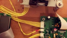
Tibi, the flat cable is twisted to access motor board but has not any bending, nevertheless i will relocate processor board closer to the motor mech.. so, i will report again after those changings..
thanks a lot")
i checked cable pins and they seem ok. i will try another cable but i have no chance within this week..
Tibi, the flat cable is twisted to access motor board but has not any bending, nevertheless i will relocate processor board closer to the motor mech.. so, i will report again after those changings..
thanks a lot
Attachments
Last edited:
I recommend a 75-Ohm Pi-pad, which requires one 125R resistor and two 140R resistors.
Hi uncle_leon,
where do you suggest implementing pi-pad, directly on the output jack or on the output pads of the board? i'm planning to put dac board in the same chassis with transport, so i'll not use any jack, should i still need pi-pad resistors and does it make sense if i implement them on the output of transport or input of the dac board?
thanks..
Hi Sean, hi Tibi, thanks..
i checked cable pins and they seem ok. i will try another cable but i have no chance within this week..
Tibi, the flat cable is twisted to access motor board but has not any bending, nevertheless i will relocate processor board closer to the motor mech.. so, i will report again after those changings..
thanks a lot
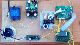
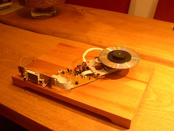
endia, what's the blue device and the board next to it?
Hi Tony, I recommend a 75-Ohm Pi-pad, which requires one 125R resistor and two 140R resistors. All of these are available from me, in both the cheaper and the "extreme" variety.
I thought from the mention of this earlier that the desired solution was to have Dout see a bit of a higher load impedance. Also, with those values isn't the signal attenuation fairly high?
A Pi-pad on the order of 1300-8.66-1300 would meet the requirements for current drive capability of Dout and have minimal attenuation of the signal.
endia, what's the blue device and the board next to it?
it's a pcb type transformer and connected to Peter Daniel's nos dac..
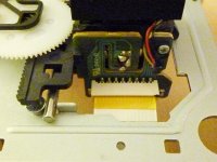
CD Sled Cable position
endia,
The CD Sled Cable appears to be fine. While it is better to have the cable not twisted, that is not the cause of the CD Sled not stopping its travel.
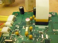
For whatever reason the processor is not seeing the "home" switch close, pins 5 and 6, which stops the motor and starts the CD read sequence. You need to move the CD Sled to close the switch and confirm it is closed with a meter and then trace the signal to the processor board at least to the "Motor" connector soldered connector pins.
endia,
The CD Sled Cable appears to be fine. While it is better to have the cable not twisted, that is not the cause of the CD Sled not stopping its travel.
For whatever reason the processor is not seeing the "home" switch close, pins 5 and 6, which stops the motor and starts the CD read sequence. You need to move the CD Sled to close the switch and confirm it is closed with a meter and then trace the signal to the processor board at least to the "Motor" connector soldered connector pins.
Sean,
for me it's impossible to measure anything within 2-3 seconds..
as seen on the video, 2-3 seconds later power on, it's arriving to cd turntable and starting to noise. i'm disconnecting the power in hurry to prevent something to get damaged.. firstly i will try another "motor" cable and move to processor board closer to the motor mechanism.. i hope it's because of the cable..
thanks a lot..
I thought from the mention of this earlier that the desired solution was to have Dout see a bit of a higher load impedance. Also, with those values isn't the signal attenuation fairly high?
A Pi-pad on the order of 1300-8.66-1300 would meet the requirements for current drive capability of Dout and have minimal attenuation of the signal.
Actually, shunt values of 1130 and a series of 10 Ohms will produce an exact 75 Ohm impedance with a very low attenuation and excellent return loss (~119 dB). It also exceeds the minimum load of 390 Ohms as indicated by GSI (post #6232). An exact impedance match and very low return loss should make for a excellent digital signal transfer.
endia,
You do not need to have the CD Transport powered up to check for the switch being closed.
You can manually move the CD Sled by turning the gear drive to the point that the tab contacts the switch and closes it. Assuming the switch closes, you can test for continuity through the cable and all the way to the processor board.
Tibi,
it's not clear on the previous picture, this is how i connected the 16 pin flat cable, is it wrong?
From what I see in your movie, the laser is not powered and from what I see in your pictures the 16pin flat cable is not fully inserted in connectors. Please check again.
Keep 16 flat cable free of any tension. This may lead to errors in operation.
Regards,
Tibi
Hi Tony, I put all of my latest recommendations in my Compiled Shigaclone Guide. Of course, not everything is covered (yet!), so please feel free to ask about any particular positions...
uncle_leon,
For your Compiled Shigaclone Guide, attached is the datasheet of CSC1469XH.
Regards,
Tibi
Attachments
I am in the process of building a third player.
This one will be called Mini PiTbull Mark II
Obviuosly I will try to upgrade there where possible starting with the SPDIF and the C906.
I will try to put it in a post....uncle Leon will provide me with " his stuff" and I will challenge a few resistor and caps in the process.
This one will be called Mini PiTbull Mark II
Obviuosly I will try to upgrade there where possible starting with the SPDIF and the C906.
I will try to put it in a post....uncle Leon will provide me with " his stuff" and I will challenge a few resistor and caps in the process.
Good luck Erik. You have certainly covered a lot of ground so far, which has been of benefit to all of us.
Are you planning on using Tibi's PS PCB with upgraded components or building your own PS from scratch?
I've been thinking that the PS and display each should probably be shielded to keep any stray emissions from getting near the player. Of course with the PS in a separate box that may not be needed, but I know some supplies work better with very short leads to the load while others are okay with longer leads. I've been wondering about the PS based on Tibi's PCB and whether it would be better positioned in a separate box, or if it is best placed close to the load.
It will be a playerboard and a seperate psu this time.
Are you planning on using Tibi's PS PCB with upgraded components or building your own PS from scratch?
I've been thinking that the PS and display each should probably be shielded to keep any stray emissions from getting near the player. Of course with the PS in a separate box that may not be needed, but I know some supplies work better with very short leads to the load while others are okay with longer leads. I've been wondering about the PS based on Tibi's PCB and whether it would be better positioned in a separate box, or if it is best placed close to the load.
It is always a " no free lunch situation" .
The idea is psu with transformer(s) rectification, line filter in the box....and regulators, clock and (swich on/off) display on the board....
I will be using the boomboxboard.....but that is mainly because I have a lot of them and I want to mutulate them
BTW I am building this for my (best) friend so he has some saying in the matter (at least I will make him think that) and he wants a small player in sight and the PSU tucked away.
The idea is psu with transformer(s) rectification, line filter in the box....and regulators, clock and (swich on/off) display on the board....
I will be using the boomboxboard.....but that is mainly because I have a lot of them and I want to mutulate them
BTW I am building this for my (best) friend so he has some saying in the matter (at least I will make him think that
) and he wants a small player in sight and the PSU tucked away.
Last edited:
Actually, shunt values of 1130 and a series of 10 Ohms will produce an exact 75 Ohm impedance with a very low attenuation and excellent return loss (~119 dB). It also exceeds the minimum load of 390 Ohms as indicated by GSI (post #6232). An exact impedance match and very low return loss should make for a excellent digital signal transfer.
Tony, the main reason we are tinkering with L-pads and Pi-pads is that signal produced by Shiga is too high and needs to be attenuated in order to meet the S/PDIF specification. See the output resistors section in my guide.
Of course with the PS in a separate box that may not be needed, but I know some supplies work better with very short leads to the load while others are okay with longer leads.
The transformer and diodes (and the first smoothing cap if using CRC filter) can be installed pretty far from the main unit - as much as 1.5m works fine. But the regulator and its supply cap and output cap should be as close to the board as reasonably possible.
uncle_leon,
For your Compiled Shigaclone Guide, attached is the datasheet of CSC1469XH.
Regards,
Tibi
Thanks Tibi! I added this to the guide.
Last edited:
Tony, the main reason we are tinkering with L-pads and Pi-pads is that signal produced by Shiga is too high and needs to be attenuated in order to meet the S/PDIF specification. See the output resistors section in my guide.
Can't get to this from work. How much attenuation is needed (in dB)?
- Home
- Source & Line
- Digital Source
- Finally, an affordable CD Transport: the Shigaclone story