I am still assembling my boards and I have found that the connector listed for j4 and j10 will only fit on the wrong side of the two boards. This would put it behind the LCD on the display board. Also the part does not seem to come with the piercer for the ribbon cable and regardless of that I can find no source for the ribbon cable in North America. Has anyone from our side of the world come up with a solution for this? If not can I purchase these parts from you Tibi? Thanks in advance. ( :
I am using the 538-90584-1318 part from Mouser.
dillmeister,
You should have in the kit one red and one white connector.
Use the red on display board and white on the main board.
If any part is missing please let me know and I´ll send to you asap, no costs from your side.
Regards,
Tibi
I had the same problem, the mouser part is just as you described it it will only go in on the wrong side. I ended up buying the red farnell one that tibi uses.
You can use mouser part on main board and farnell on display board.
Regards,
Tibi
Hi Tibi,
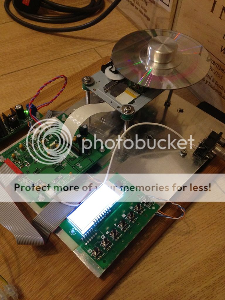
Just received the Mounted and tested Shigaclone today, will start work tomorrow. Thanks!
Also been looking for a appropiate case and found something like this at 40US$ plus shipping, not sure if it will fite the Shigaclone plus a ES9023 DAC with power supply:
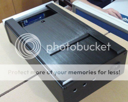
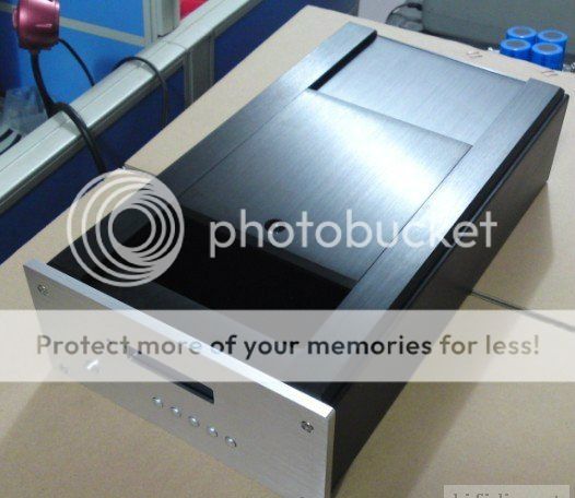
Exterior:W226H100D391
Interior:W203H84D380 (all in mm)
Will need to ask the factory if the front buttonu can be relocated and mounting holes can fit the display or not.
Just received the Mounted and tested Shigaclone today, will start work tomorrow. Thanks!
Also been looking for a appropiate case and found something like this at 40US$ plus shipping, not sure if it will fite the Shigaclone plus a ES9023 DAC with power supply:
Exterior:W226H100D391
Interior:W203H84D380 (all in mm)
Will need to ask the factory if the front buttonu can be relocated and mounting holes can fit the display or not.
 , good job man! 40US$ only, it's cheap for a case like this!
Hi,
I found this from one of the taobao store in China that I bought a case for my chipamp before, I havn't order this case yet. The seller seems quite nice and the price is very good. It was original designed for a CDM9 transport.
90¸ß¶¥ÍƸÇCDM9תÅÌ È«ÂÁ»úÏä-ÌÔ±¦Íø
I found this from one of the taobao store in China that I bought a case for my chipamp before, I havn't order this case yet. The seller seems quite nice and the price is very good. It was original designed for a CDM9 transport.
90¸ß¶¥ÍƸÇCDM9תÅÌ È«ÂÁ»úÏä-ÌÔ±¦Íø
Hi Tibi,
Few question after checking the stuffs before start putting thing together:
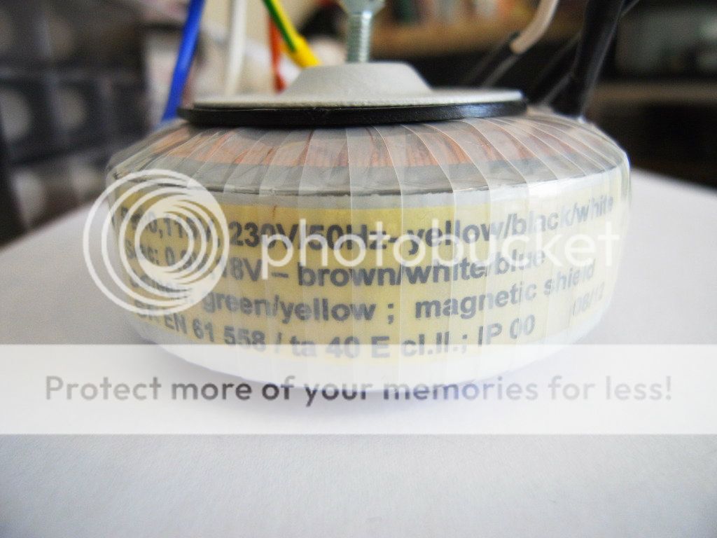
1. The transformer shown seconday: 0, 9V, 18V (brown, white, blue), is the transformer provided has 2 secondary windings or center taped ? How should I connect it to the PS modul?
brown -> J7-1
White -> J7-2
Blue -> J7-3
2. The March and September version differ alot on the regulator for V1, V2, V3 and V4, Do we need those 4 separate regulators? I don't see any proviision for them on the power supply module and neither on the main DPS module, please kindly enlighten me. What will be the impact on the output quality with and without those 4 regulators?
Is there an option on the main module for supplying the 4 regulated power and are they all expected to be 5V?
3. What is the total current drawn ?
Thanks and regards
Few question after checking the stuffs before start putting thing together:
1. The transformer shown seconday: 0, 9V, 18V (brown, white, blue), is the transformer provided has 2 secondary windings or center taped ? How should I connect it to the PS modul?
brown -> J7-1
White -> J7-2
Blue -> J7-3
2. The March and September version differ alot on the regulator for V1, V2, V3 and V4, Do we need those 4 separate regulators? I don't see any proviision for them on the power supply module and neither on the main DPS module, please kindly enlighten me. What will be the impact on the output quality with and without those 4 regulators?
Is there an option on the main module for supplying the 4 regulated power and are they all expected to be 5V?
3. What is the total current drawn ?
Thanks and regards
Skylab,
If the seller is able to make a custom front panel, this case would be great for the shigaclone. Be sure many people would be interested for this
Envoyé depuis mon Nook Color avec Tapatalk
I will try to find out from the seller if if this is possible and get back on this.
Hi Tibi,
Just received the Mounted and tested Shigaclone today, will start work tomorrow. Thanks!
...
Thank you for confirmation.
Regards,
Tibi
Hi Tibi,
Few question after checking the stuffs before start putting thing together:
1. The transformer shown seconday: 0, 9V, 18V (brown, white, blue), is the transformer provided has 2 secondary windings or center taped ? How should I connect it to the PS modul?
brown -> J7-1
White -> J7-2
Blue -> J7-3
2. The March and September version differ alot on the regulator for V1, V2, V3 and V4, Do we need those 4 separate regulators? I don't see any proviision for them on the power supply module and neither on the main DPS module, please kindly enlighten me. What will be the impact on the output quality with and without those 4 regulators?
Is there an option on the main module for supplying the 4 regulated power and are they all expected to be 5V?
3. What is the total current drawn ?
Thanks and regards
Hi,
1. This is documented in Shiga datasheet https://docs.google.com/document/d/1vlabZc_1If3x12ox2A5ECZxC0HLGnuOWdM-j9X4b7Q0/edit
2. March and September version differ because we made several versions and tests before last release.
The version story is as follow:
Version 1 was the version with separate regulators LT1763 for each section.
Finally we concluded that the benefit of these regulator is quite low and even in a very expensive systems the difference do not justify the investition. Beside this, LT1763 trend to oscillate at very high frequency if not decoupled with at least 100nF ceramic. And I do not like large Z5U/X7R ceramics due their piezoelectric effect.
So we have designed Version 2 which was a one to one clone of the JVC RC-EZ31. However, the clone had several modifications as follow:
- original Sanyo LA6541 instead CSC1469XH clone.
- internal DAC and analogue output removed
- option to use an external can oscillator or internal LC78601
- option to power each section from external regulators or use a ferrite bead to bypass.
All went ok, except that we had several bugs in PCB design, so we corrected this in
Version 3 which is the current one and was presented also on diyaudio forum.
All regulator sections for V1, V2, V3 and V4 are optional and therefore it's your option which regulator to use and what section to power from an external source.
We have mentioned this several times on forum and I personally consider this is the best way. People have different preferences and "tastes" for a specific regulator. Remove the ferrite bead and use your preferred reg.
3. We did these measurements for original JVC. I made the measurements for Shiga as well but only for separate sections and for different operation (no play, play first track and play last disk track) I'll look for results and post here.
Regards,
Tibi
Hi Tibi,
Is heat sink needed for LA6541? Cannot find it from the kit.
Thanks
Hi,
The pcb was designed to take over LA6541 heat dissipation and is not included in the kit. But in case your housing is closed and/or do not allow enough air flow, you may need an extra heatsink. Please have a look in documentation.
Regards,
Tibi
Hi,
The pcb was designed to take over LA6541 heat dissipation and is not included in the kit. But in case your housing is closed and/or do not allow enough air flow, you may need an extra heatsink. Please have a look in documentation.
Regards,
Tibi
Understood. I will try without heat sink first since I haven't decided on case and airflow is not an issue yet. Spent the night making those cables, the connectors are just too small for my eye, made many mistakes and ran out of those connector already. Need to buy them from local store tomorrow.
Thanks.
Anyone have an RDEZ11??
I've seen mention of the RDEZ11 but I can't see any posts about the innards and if it might be suitable.
Is anyone able to get a service manual for the RDEZ11?
After all this time I was hoping to find something to hack!
Oh well, maybe next time ;-)
Herb
I've seen mention of the RDEZ11 but I can't see any posts about the innards and if it might be suitable.
Is anyone able to get a service manual for the RDEZ11?
After all this time I was hoping to find something to hack!
Oh well, maybe next time ;-)
Herb
- Home
- Source & Line
- Digital Source
- Finally, an affordable CD Transport: the Shigaclone story