Hi TheGimp,
I'm pretty much at the same place as you, except that I broke a leg off of the laser transistor Q2 IIRC, and I'm still waiting for replacement.
In the mean time I reflowed all solder joints on passives and once I had done that I actually did as suggested by danzup and re-soldered all IC's.
I have also sourced another mechanism (puck less).
Where did you source your components? do you have the mouser crystal? what loading's have you tried? data sheet for this crystal says (need to specify requirement). So far I have tried 8pF and 18pF also tried no crystal for comparison resulting in no TOC read.
Once replacement transistor arrives I will resume testing where I had left off.
Things I am going to try:
1. alternative mech
2. proper crystal CSA-309 8pf loading
3. wait for someone cleverer than me to give awnser.
Please keep us posted on your progress, good look troubleshooting.
Last edited:
I built the Full Shiga Kit, so I should have all the correct components.
My second unit I'm building from a pwb set and the SS devices and supplying my own resistors, capacitors, etc.
My concern is I may have miss-placed capacitors which could effect timing.
I'll start looking at signals next I guess.
My second unit I'm building from a pwb set and the SS devices and supplying my own resistors, capacitors, etc.
My concern is I may have miss-placed capacitors which could effect timing.
I'll start looking at signals next I guess.
@ The Gimp and @ Blueworm :
this week someone (I prefer not to say names) assembled a Shiga from Vicol audio . After assembly he observ that his shiga behave exactly as your unit.Then he bring this to me.
After checking the resistors ,visual that are in value and place correctly and hope that capacitors are correctly mounted, as I was not eager to desolder and measure every each of capacitor, I began to solder each component and also all IC on that board .
After that, testing : work like charm and as intended !!!
So after soldering over 15 piece of Shiga (wich all fired up and working from the first time ) and debuging another unit wich after my "touch" began to work ,I have only one advice for you : magnifier and eyes can lie to you , just solder with big blob of solder every smd component and watch for short circuit !!!!
P.S.: both if you cannot made this kit working contact me on pm and if you pay for delivery to me and back I will debug for free your board .
Attachments
Last edited:
Thank you danzup for the wonderfull offer, its nice to have a safety net. As I mentioned in my earlier post I resoldered all passives and contrary to my earlier comment I did go ahead and resolder all IC also. Now awaiting spare Q2 to continue testing. Elf honor is at stake! (Ben and holly's little kingdom).
Thank you for your offer danzup. Hopefully I will be able to resolve the problem myself but it is good to know I have the option of your offer.
I'm going to print out a large copy of the schematic and go through the data sheets to analyze each component for critical value positions.
Resistor values have already been confirmed, so they will be visually inspected again using a 10X stereoscope at a SMT solder station.
During soldering, I was able to observe solder wicking under each IC pin to pad junction so I believe the connections are good, but will re-solder them as that is easy to do.
Wrong value bypass caps for instance should not cause this problem, but electrolytics are easy to evaluate and change.
100nF bypass caps can not be evaluated on board, but can be ignored on a first pass.
I suspect a wrong value/poor solder connection at an RC filter causing a time constant to be wrong. I tried measuring capacitors on board, but got erratic readings. Some were wildly off and I suspect this was due to circuit loading.
I would really like to identify the exact component (or at least sub-circuit) responsible for this behavior, so that we can document it in the case others have the same issue, since it appears that at least three boards have exhibited this problem.
If my second board functions when complete I'll have a reference to compare to, but it will take several weeks before I finish it.
I thought about doing a matrix of static voltages but I suspect that would not be very useful.
Timing is going to be difficult to analyze since this is a start-up issue.
Back to visual inspection and re-soldering.
Tibi: when are you expecting to send out the fully assembled kits? Maybe you've said this already, sorry if I've missed it...
Fran
Hi Fran,
I already started.
I don't want to promise, but I'm doing my best to have GB closed this month.
Regards,
Tibi
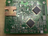
R19 R28 R27 R19 R8 R9 R38 R31 R13 R15 are not ok ( on solder ) as seen in your photo !
Please use more solder and flux on all resistors an capacitors.
If i want to take a guess about the subsystem that do not work ,it is about resistors and capacitors near the LA9242 or resistors and capacitors that take signal from LA and routing to LC .
Please use more solder and flux on all resistors an capacitors.
If i want to take a guess about the subsystem that do not work ,it is about resistors and capacitors near the LA9242 or resistors and capacitors that take signal from LA and routing to LC .
Last edited:
TheGimp,
I had a close look on your board.
R1 and R17 must be 27K while on your boards looks like you have 43ohm, but the image is not very clear.
However, I'm sure that these resistors are not from the kit I sent to you.
Also, please check soldering for C16, R19 and R5.
Regards,
Tibi
I had a close look on your board.
R1 and R17 must be 27K while on your boards looks like you have 43ohm, but the image is not very clear.
However, I'm sure that these resistors are not from the kit I sent to you.
Also, please check soldering for C16, R19 and R5.
Regards,
Tibi
Thanks Tibi,
I'll see if I can get either at the local electronics shop tomorrow.
I installed two 500pf Silver Mica in parallel, same results.
Don´t forget to chk R1 and R17, these must be 27K.
Regards,
Tibi
Well, now this is strange.
I re-soldered the ICs although I believe there was no issue with them. I also inspected every component for integrity of the solder joints and I am sure they are fine. This was done at a SMT solder station on proper equipment, not just with a magnifying glass.
I did change R1 and R17 to be sure they are correct.
Tried it again and same results.
Then I thought...... Maybe it does not like "RETURN TO FOREVER - THE MOTHER SHIP RETURNS".
So I tried "chick corea . return to forever"...
ba-da-bing! Digital data out.
I have not hooked up a D/A yet but will try it later tonight.
So it works, but is marginal and it is finicky about what CD it plays.
.....
Edit - I tried the offending CD in another player.
.....
I got the CD set a couple of weeks ago and listened to the first two CDs.
HA! The CD won't play in any of my CD players (3) so it is a bad CD I guess. I'll have to try a bunch of other CDs to be sure but it might be that the CD was my problem all along!
Last edited:

Waiting patiently for my mounted Shiga….
Appreciate very much your patience.
This week 3 ready mounted Shiga´s have been already shipped and another 8 are waiting to be packed and shipped.
Each delivery is announced by mail with a postal receipt copy.
Just a reminder, all Shiga documents are available at http://vicol-audio.ro/shiga.php
Regards,
Tibi
- Home
- Source & Line
- Digital Source
- Finally, an affordable CD Transport: the Shigaclone story