Ok will doHi Blueworm,
Before further tests, could you please check your solderings.
Regards,
tibi
")
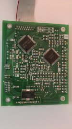
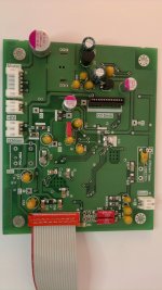
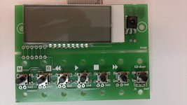
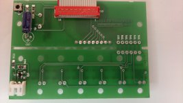
I have made few pictures of a finished ready mounted and tested kit.
Please use them as comparition.
Please also note the lased is not visible with direct eye. See movie Ready mounted and tested Shiga kit - YouTube
Regards,
Tibi
Please use them as comparition.
Please also note the lased is not visible with direct eye. See movie Ready mounted and tested Shiga kit - YouTube
Regards,
Tibi
Attachments
I love your demo CD. What is it?
Tsuyoshi Yamamoto - Autumn in Seattle CD
Tsuyoshi Yamamoto - Autumn in Seattle CD Album
YAMAMOTO TRIO AUTUMN IN SEATTLE ULTRA HD CD-Elusive Disc
I´ll send you a copy with the kit, than you can buy the original it is a FIM XRCD recording.
Regards,
Tibi
Hi Blueworm,
Before further tests, could you please check your solderings.
Regards,
tibi
HI Tibi, I've just inspected all solder joints with a magnifing glass and all seem ok. The laser can be seen in the camera if you get it a little closer. Bad news, I broke a leg off Q1 (2SA608NF). Any Chance I can buy a replacement from you? as they are very hard to find, or can you suggest a replacement. My trouble shooting is now on hold until this is replaced. Thank you for your help so far.
HI Tibi, I've just inspected all solder joints with a magnifing glass and all seem ok. The laser can be seen in the camera if you get it a little closer. Bad news, I broke a leg off Q1 (2SA608NF). Any Chance I can buy a replacement from you? as they are very hard to find, or can you suggest a replacement. My trouble shooting is now on hold until this is replaced. Thank you for your help so far.
If I where in you place , I will do solder again the legs of the 2 IC LA and LC and all resistors and capacitor on that board , regardless they look ok on a looking glass.
And i say that after many years of servicing SMD boards ....
If I where in you place , I will do solder again the legs of the 2 IC LA and LC and all resistors and capacitor on that board , regardless they look ok on a looking glass.
And i say that after many years of servicing SMD boards ....
Ok I can re-flow the passives but I really dont want to apply more heat than neccessary to the IC's.
I'll probe IC's to nearest pad or via.
Thanks danzup
Tsuyoshi Yamamoto - Autumn in Seattle CD
Tsuyoshi Yamamoto - Autumn in Seattle CD Album
A great group. I have a few of their CDs. I didn't get this one because IMO a lot of the standards on the disc are really not that great.
I've just spent the last couple of days looking through this thread and must say I am very impressed with the results people have achieved.
I can't figure out exactly what tvicol is offering everyone however. From what i can see it is a redesigned controller board for the cd mech, is that correct?
Also, is it possible to purchase just the pcb for the mech + the lcd display?
Thanks
I can't figure out exactly what tvicol is offering everyone however. From what i can see it is a redesigned controller board for the cd mech, is that correct?
Also, is it possible to purchase just the pcb for the mech + the lcd display?
Thanks
Hi Shigaclon People
tonyptony a few pages ago make a good propound to migrate on
//www.diyaudio.com/forums/digital-source/217177-using-new-2012-shigaclone-create-killer-high-end-transport.html
In that way I thing we accent the great job of tvicol.
Also ease way to make compare JVC EZ31 and new made board.
Do you???
Regards
Last edited:
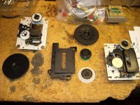
I tore apart a couple of CD-rom drives, and two junk boom boxes (one free the other $5 ad a thrift store).
Here is a pix of the pucks. The CD-Rom drives all used small diameter pucks with magnets that measured less than 1cm in diameter. Despite the size, they were quite strong and able to lift the counterpart from as much as 1cm distance. Regrettably, the shaft diameter on teh CD-Rom drives is larger than the diameter on our transports so the complete puck assembly will not transfer.
The boom boxes used much larger pucks. One boombox used a 15 pin version of the transport which is almost identical to the one we are using. It is so close, I am able to use the puck (leftmost in pix) and the plastic laser shield from it's transport on the transport I got with my complete kit.
This chuck has a pad on the bottom to help prevent the CD from slipping.
The boom box also provided several connectors, a split bobbin shielded power transformer, rubber shock mounts for the transport and other useful components.
Attachments
blueworm, did you ever resolve your problem?
My unit does essentially the same thing.
Power up with door switch open, unit spins with "00" display.
Place CD and puck in place, switch door switch closed, unit goes to blinking "- -" 11 times during which the platter spins, sled seeks and laser focus operates, then it goes to "00" .
Laser is functioning as verified with a camera with no CD in place.
No front panel switches cause any operation of the unit.
LCD contrast is poor and one has to look at a shallow angle to see the difference between active and inactive segments.
I installed a pot for the LED intensity and it helps a little.
How do I adjust contrast?
My unit was assembled on a SMT workstation, then cleaned and inspected for solder faults under a stereo microscope. None present.
Resistor placement was verified for both my boards (second still missing connectors, etc) by measuring the components on the board.
Last edited:
As an added note, I watched the transport and noticed that the tracking mechanism was performing a lot of tracking adjustment, so I swapped transport to another I had. The first unit had over one tooth variance in tracking. The second almost none.
I still get the same results, so I think I can rule out the transport as the problem.
Yes, I re-applied the solder short for the LASER of the first transport before disconnecting it, and removed the short from the second transport after wiring it up.
Pre-Regulator output is 8.02V
V1 = 5.01V
V2 = 5.01V
V3 = 5.02V
V4 = 5.02V
TP1 = 2.55V
TP2=4.74V
Last edited:
- Home
- Source & Line
- Digital Source
- Finally, an affordable CD Transport: the Shigaclone story