Hello Jac,
Your memory is OK.") 8V are for motor drive.
8V are for motor drive.
V1, V2, V3, and V4 have been designed to power each IC section separately.
LA9242M use a internal resistor divider 20K + 20K to generate Vref=2,5V. This internal divider is noisy and if you add an external, extra, divider you improve noise and stability.
The S/PDIF board will be treated separately and is a work on progress.
Regards,
Tibi
Your memory is OK.
8V are for motor drive.V1, V2, V3, and V4 have been designed to power each IC section separately.
LA9242M use a internal resistor divider 20K + 20K to generate Vref=2,5V. This internal divider is noisy and if you add an external, extra, divider you improve noise and stability.
The S/PDIF board will be treated separately and is a work on progress.
Regards,
Tibi
Awesome news Tibi. Have you been able to compare it to any of the well known mega transports (ML 31.5, CEC, Linn CD12)?
BTW, I should have asked this a while ago when I signed up, but in order to build 1 of these, do I ask for "1" of every line item on the list?
We have a Wadia 21, Unico CDP, Accuphase DP-800 and various other transports, but please, do not put me in position to review my own project. I'm not that kind of man. All I can say is that Shiga is simple fantastic and we must thank to Junji Kimura for geniality and Peter Daniel for sharing this great project with the world.
Regards,
Tibi
We have final price from PCB factory.
Boards are FR4, 1.6mm, 70um Cu
All three boards are 18euro - TVA included.
We will start to receive money starting with 09.July. Those who do not ordered LCD may contact us for payment details.
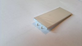
In the meantime we should receive and test LCD samples.
Regards,
Tibi
Boards are FR4, 1.6mm, 70um Cu
All three boards are 18euro - TVA included.
We will start to receive money starting with 09.July. Those who do not ordered LCD may contact us for payment details.
In the meantime we should receive and test LCD samples.
Regards,
Tibi
All looking great!
Well done!
'O tsukare samma!' as we say in Japan...
I'm getting itchy soldering fingers!....
I will also need to look at power supply options and recommendations.
Bill
Thank you !
We have a Wadia 21, Unico CDP, Accuphase DP-800 and various other transports, but please, do not put me in position to review my own project. I'm not that kind of man. All I can say is that Shiga is simple fantastic and we must thank to Junji Kimura for geniality and Peter Daniel for sharing this great project with the world.
Regards,
Tibi
Fair enough, Tibi. And I agree - thanks to you and the team, and Junji and Peter!
Getting back to the order list, I want to make one but I want to be sure of having spares for the items which might be likely to either need replacement over time or might be easily damaged by careless assembly. How many of each item should I get?
The single component which may need replacement is CD mechanic. For the time been, all cd mechanics we have are with original Sanyo laser (SANYO DL-3150-101) and KODENSHI: PIC–6710 pin diodes. I would keep one for spare. ;-)
Regards,
Tibi
Last edited by a moderator:
Hi Tvicol Ref the ready made kit fully tested ,,,,,,,,,,do you have a price in mind yet ,,,, regards john
As I see it just add the prices in the bom which you have to find yourself... Then add postage.
Brgds
Hi Tvicol Ref the ready made kit fully tested ,,,,,,,,,,do you have a price in mind yet ,,,, regards john
Full KIT and ready made shigaclone will be sold only trough vicol-audio webshop.
Around middle of July I'll announce the price and the webshop will be open at 1st August.
Regards,
Tibi
As I see it just add the prices in the bom which you have to find yourself... Then add postage.
Brgds
The BOM is for those who want to buid shiga from scratch.
We have selected components for you.
On other hand, we are working on documentation and will be made available for all public here.
As this is a DIY project I expect people to buy only PCB and hard to find components.
Regards,
Tibi

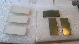
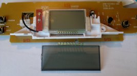
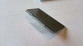
Multiplexed LCD was the bottleneck of this project. It is the most hard to find component and we had to design and produce a new one from scratch. This have delayed project a lot, but I'm very statisfied to see we have passed this "test".
I would also like to confirm that the final price for LCD is 6euro.
Regards,
Tibi
I would also like to confirm that the final price for LCD is 6euro.
Regards,
Tibi
An Alternate Aprroach to the 5V Power Supply
With the potential oscillation/vibration issue on the 5V LT1763 regulators, I've been thinking about alternative approaches. I've been thinking about using this one that I will call the Jos Buffer Regulator. I ran into this one on Jos Van Eijndhoven's Relaixed2 pre-amp. It's cool for a low current, low voltage application like this because it uses one voltage regulator chip and zener for the reference voltage and then uses op-amps to buffer each voltage output.
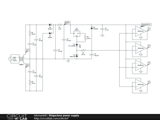
One caution is that the regulator op-amps can oscillate at high frequencies if their is bypass capacitance at the input of the IC.
I have shown OPA551 op-amps in the schematic, but you many op-amps can work, as long as they are unity gain stable and have reasonable GainBandwidth.
Output should be very low impedance. A simulation in circuit lab says that the S/N should be 157 dB compared to the 5 volt output. That is probably optimistic, but it looks pretty good to me.
I would appreciate any comments on experience with this or similar circuits. Of course, I may just have to build it and see how it works.
With the potential oscillation/vibration issue on the 5V LT1763 regulators, I've been thinking about alternative approaches. I've been thinking about using this one that I will call the Jos Buffer Regulator. I ran into this one on Jos Van Eijndhoven's Relaixed2 pre-amp. It's cool for a low current, low voltage application like this because it uses one voltage regulator chip and zener for the reference voltage and then uses op-amps to buffer each voltage output.
One caution is that the regulator op-amps can oscillate at high frequencies if their is bypass capacitance at the input of the IC.
I have shown OPA551 op-amps in the schematic, but you many op-amps can work, as long as they are unity gain stable and have reasonable GainBandwidth.
Output should be very low impedance. A simulation in circuit lab says that the S/N should be 157 dB compared to the 5 volt output. That is probably optimistic, but it looks pretty good to me.
I would appreciate any comments on experience with this or similar circuits. Of course, I may just have to build it and see how it works.
CircuitLab Link
I realize that the schematic is pretty small in the forum, so here is a link to it on CircuitLab. There, you should even be able to simulate the output of the model.
https://www.circuitlab.com/circuit/9hc6rf/shigaclone-power-supply/
I realize that the schematic is pretty small in the forum, so here is a link to it on CircuitLab. There, you should even be able to simulate the output of the model.
https://www.circuitlab.com/circuit/9hc6rf/shigaclone-power-supply/
I realize that the schematic is pretty small in the forum, so here is a link to it on CircuitLab. There, you should even be able to simulate the output of the model.
https://www.circuitlab.com/circuit/9hc6rf/shigaclone-power-supply/
Thank you lehmanhill for this contribution.
As the shiga already sound very impressive , we decided to go for a classic approach. This mean that all LT1763 regs will be on the power supply board. Final decision will be at the end user to use them or not.
This not exclude the possibility to include discrete series/shunt regulators.
The board will have separate pads and markers for each power supply you may use with an aux supply or not.
Regards,
Tibi
I recently tried out some resistors made by Uncle_Leon in my shigaclone, specifically testing them against the RF attenuators that I have been banging on about here for the past year or so. Well, against all my expectations, the resistors I think have the edge on sound quality.
Before this I had tried a good number fo different types of resistors on the shiga output and the RF attenuator easily beat them all. Now Uncle_Leon comes along and upsets the world order.......
So what differences do I hear? Well, for one, the midrange is a bit more smooth. Things like voices are more rounded and real, cello you get more of the tone and wood of the instrument. Putting back in the RF attenuator, you can hear a slight thinness by comparison. Bear in mind that the RF attenuator beat all other resistor types up to now. As I mentioned, I was not expecting them to come anywhere close.....
Fran
Thanks for sharing your observations Fran, I am glad you liked my resistors! Too bad you could not listen to my stepped attenuator made with these beauties
- out of this world transparency, and dynamics to die for!Now, regarding:
Following a suggestion from spartan, I am planning to investigate the hypothesis that Fran's attenuator sounds better than an L-pad made with standard resistors because the Pi-pad configuration is inherently better than an L-pad.
So I need a Pi-pad that has the same parameters as the 300/100 L-pad, and this is where things get a little tricky with my limited understanding of impedances...
I am guessing I should go for a Pi-pad calculated for 75Ohm input, 75Ohm output and 12dB attenuation (2V/0.5V=4 ->12.04dB) - is this right? That would mean two 125R shunt resistors (R1 and R3) and a 141R series resistor (R2) - could someone please confirm?

I have just finished listening to the two resistor configurations, and had to write about it immediately - I was too excited to sleep before sharing my findings
But first things first, the experiment conditions:
Both 'pads were made with my hand-made resistors, but not the "Invisistors" - I used simpler and less refined resistors (which nevertheless sounded better than nude Vishay
). I assumed absolute quality did not matter, as long as it was consistent.The L-pad resistors' values were accurate to <1%, which is probably better than what most people use - and which does not really matter because the resulting impedance is not matching anything at all.
The Pi-pad series resistor (140R) was also accurate to <1%, and the two shunt resistors (125R) were matched pretty much as closely as my multimeter allows (within +-0.1R). In this case, using accurate values actually had sense, because the impedance of the chip output is 75R, and the input impedance of my DAC is also 75R. So firstly, achieving input and output impedance of 75R would reduce reflections coming to and going out from the 'pad. Secondly, having identical input and output impedance ensures there are no reflections within the Pi-pad.
So much for the theory - now, for the results... I have to say, prior to listening I was somewhat unsure whether the difference (if any) would be noticeable. But oh dear, noticeable it was, no doubt about that! It could all be summed up in just one word: clarity. The Pi-pad is decisively more clear. Despite using inferior resistors (compared to the ones I use for everyday listening), I actually heard a few nuances I never noticed before! This configuration gives each sound better definition - attack is more clear and pronounced, and decay and subsequent echoes are more easily discerned. This of course boosts the soundstage, allowing you to hear better where each instrument is positioned, and how far it is from the microphone. I could hear no change in timbre or tonal balance, the sound was just less veiled.
It would be great if someone else could confirm this, although the difference is such that I am 100% confident as to my findings: Pi-pad is better.
More listening will be required to develop the optimal resistor choices for this new configuration. I am guessing Vishay for the series position and Caddock MK132 for the shunts will be a good starting point. The closest commonly available values are 150R series and 120R shunts.
This would probably be a good time to announce that, as a fruit of my recent trials, I can now offer a new, much cheaper resistor type
The construction is greatly simplified, which means I need much less time to make one. The materials are still 100% natural. The sound - I compared it to a nude Vishay, which is known for its extreme detail resolution: the new resistor only had slight advantage in the sheer amount of detail, but had a lot better dynamics, and gave richer, more natural timbres. I feel it also has better bass (Vishay tends to sound a bit thin in comparison).
The price I am planning to ask for it, is £13.50 with free worldwide postage. So essentially, you pay Vishay money, but get better-than-Vishay sound. And, of course, I can make any resistor value, so you can get that perfect 75Ohm impedance
. I will put some pictures on my website soon (which is in bad need of updating anyway!  ).
).Ok, off to sleep with me, the sun is on the rise already...
- Home
- Source & Line
- Digital Source
- Finally, an affordable CD Transport: the Shigaclone story