Hi Dr.H,
Clipped section of the C906.
Clipped section of the C906.
Hi Dr.H,
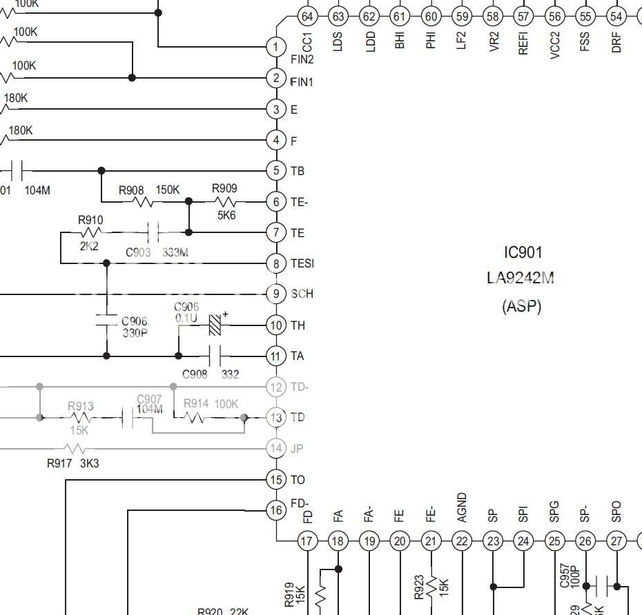
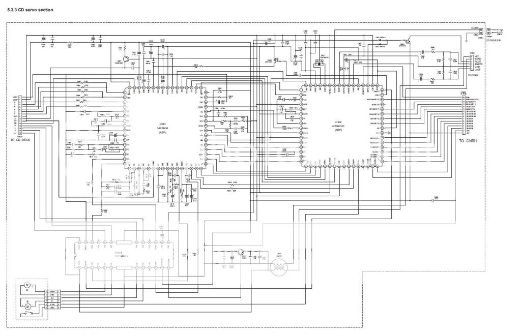
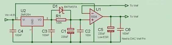
There seems to be a typo in the RCEZ31 document. There are 2 C906, one with 330P and the other one is 0.1U. So the the From Vref and To Vref should connect to the C906;s positive leg which is connected directly to the pin 10 (TH) of the IC901 LA9242M. Is it correct?
I have posted a few questions about Rubidium clocks for our clone on a lot of fora over the world.
Unfortunately no one answers (even not from guys who tell they are busy or going to be busy with those clocks) also an aggresive post from a commercial clock guy we all know....(something to do with "camping" )..must have done something wrong to him in the past...
Anyway in order to be able to ask questions one has to become a member and tell about himself...etc.
Here is one of my links this time "in english" where I introduced myself and posted pics of some diy homebuilt stuff maybe fun to read...
Hi There...My homebuild stuff - The Art of Sound Forum
Unfortunately no one answers (even not from guys who tell they are busy or going to be busy with those clocks) also an aggresive post from a commercial clock guy we all know....(something to do with "camping"
)..must have done something wrong to him in the past...Anyway in order to be able to ask questions one has to become a member and tell about himself...etc.
Here is one of my links this time "in english" where I introduced myself and posted pics of some diy homebuilt stuff maybe fun to read...
Hi There...My homebuild stuff - The Art of Sound Forum
so Is this the one being used?
Is this the vref being used in the shing a clone,
How are you adjusting it with a LM317?
Is the drawn schematic not the right location to pin 10 or 906 .1 cap
and vref in and out connect to the same place + 906 .1 cap? ,
where is the best place to supply the vref from?
Some one care to make me a drawing,Please!!!!
This all is getting confusing,
Thanks!
Attachments
Last edited:
you need to get a switch
hi,
Get a regular switch(on/off )ON is normal and 2 wires and solder it on the traces,just turn it off and back to on and your in business!
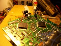
I hooked up a switch directly to the board, picture enclosed,a cherry or any small switch will work.
hi,
Get a regular switch(on/off )ON is normal and 2 wires and solder it on the traces,just turn it off and back to on and your in business!
I hooked up a switch directly to the board, picture enclosed,a cherry or any small switch will work.
Attachments
Last edited:
I've got a no/nc switch that I was going to use with the shigaclone.
But one of the pinhole traces fell off when I tried soldering up a wire to it.
I might be able to follow the trace a bit further down, or exposing part of the trace, but I'm worried I might really mess it up.
But one of the pinhole traces fell off when I tried soldering up a wire to it.
I might be able to follow the trace a bit further down, or exposing part of the trace, but I'm worried I might really mess it up.

@BMW850
This picture may be clearer where to add 5V, (point 5A). The switch is only needed if you wish to compare between original supply and a new, separate 5V supply.
I read from Peter that the 5V can be added by tap into the L901 after removing it.
Peter,
After you removed the choke L901, do you have to put 2 jumper wire there to reconnect the trace line?
Thanks
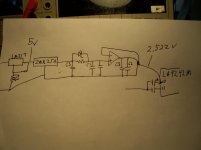
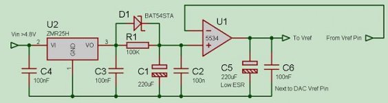
Out of curiosity, I ran the circuit as JOHNW presented it (i.e. no power supply). To my surprise, the output was holding at 2.5V.... so the short answer is there is no need for a powersupply to run the NE5534 off +-5V!!
Are you seriously saying that you ran a "regulator" circuit with no power to the error amp??? If so, it wasn't regulating anything, and any voltage you measured on the output was coming from somewhere else.
I would agree. It would certainly be more in line with the normal application note for op-amps.
Still, I measured 2.5Vout without the Vss and Vcc being supplied to the op-amp. In addition, I was able to adjust this output voltage (at pin 6 of the op-amp) through adjsuting the pot connected to the LM317 I was using.
Still, I measured 2.5Vout without the Vss and Vcc being supplied to the op-amp. In addition, I was able to adjust this output voltage (at pin 6 of the op-amp) through adjsuting the pot connected to the LM317 I was using.
- Home
- Source & Line
- Digital Source
- Finally, an affordable CD Transport: the Shigaclone story