The platter height on a lot of these cheap mechanisms is simply a matter of pulling or pushing the platter ring on its interferance fit shaft.
I was given a quite expensive Sony unit recently because it was 'broken'; all it needed was the platter raised by about a millimeter to get it working perfectly
I was given a quite expensive Sony unit recently because it was 'broken'; all it needed was the platter raised by about a millimeter to get it working perfectly
Can I adjust the platter height ??
JC
Yes, you just need to know what it should be to a convenient reference point. If you purchase a replacement mechanism you can measure from the rail or mechanism chassis to the platter on that mechanism and check that it is the same on the old mechanism..
The platter can be carefully pulled off and replaced - and I have done this, so it can be moved on its shaft relative to the laser. You need to grip the motor shaft with needle nose pliers before pushing or pulling on the platter. If you have not disturbed your platter height somehow then you probably need to look elsewhere for the problem.
Make sure there is nothing amiss with the reworks you have done to the board.
The platter ring is glued to the shaft, so without special tooling it's hard to move it. Besides, it should be self adjusting (fixed shaft length, platter pressed to the end)
Mine are all interference fit, no glue in sight. Platter is pressed nearly, but not quite to the end. Incorrect height settings caused by tinkering have caused me some minor issues quickly resolved by moving the platter slightly up or down on the motor shaft as necessary. Shaft must be clamped and no force applied to the motor or it will be damaged. (From experience)
Yes, thanks so far for all those valuable hints
I found this tool after all this time, can be used in the future to replace the original platter and puck
HobbyKing Online R/C Hobby Store : Turnigy 25mm Flywheel Removal Tool
JC
I found this tool after all this time, can be used in the future to replace the original platter and puck
HobbyKing Online R/C Hobby Store : Turnigy 25mm Flywheel Removal Tool
JC
Yes, the proper tool is necessary, here's what I was using: http://www.diyaudio.com/forums/digi...ransport-shigaclone-story-84.html#post1580109
Design dimensions and tolerances in a previous post.
http://www.diyaudio.com/forums/digital-source/120229-finally-affordable-cd-transport-shigaclone-story-post1747150.html#post1747150
Henjo
http://www.diyaudio.com/forums/digital-source/120229-finally-affordable-cd-transport-shigaclone-story-post1747150.html#post1747150
Henjo
Hi guys, I don't think anyone has done this before ")
LCD incadescent bulb mod:
I always loved the style of VU meters on my old NAD 3030 amp, backlit with actual little bulbs, so I swapped the LED in the display board for a 12V subminiature bulb (got it from Maplin, cost me a whopping £1 or so).
At the minute I'm feeding the bulb directly off the transformer, which makes it quite bright (I think I'll add a pot for changing brightness) - this also has an added bonus of bringing the transport "alive": it dims a bit on each seek or stop, it also dims intermittently when the reader is struggling with a scratched CD, or generally does something other than read or idle (I'm guessing this is because of poor regulation of the boombox transformer). In any case, I like the effect very much
The black thing covering the light is aluminium foil - the bulb didn't quite fit in the LED hole, so I couldn't use the stock plastic "cover". Cutting a bit of plastic should easily solve this, I just didn't get round to doing it yet.
Also, I took out the white piece of plastic sheet from behind the LCD (the one acting as a light diffuser of sorts) - I think it makes the display look boring. Without it, it looks kind of old school with the visible vertical glass "stripes", which I like.
Oh, and in case anyone is wondering - the bulb does get pretty hot, but not terribly so, and it doesn't seem to melt anything around it, or smell, or cause any other problems. I've had it running constantly all day today and all is fine
LCD incadescent bulb mod:
An externally hosted image should be here but it was not working when we last tested it.
I always loved the style of VU meters on my old NAD 3030 amp, backlit with actual little bulbs, so I swapped the LED in the display board for a 12V subminiature bulb (got it from Maplin, cost me a whopping £1 or so).
At the minute I'm feeding the bulb directly off the transformer, which makes it quite bright (I think I'll add a pot for changing brightness) - this also has an added bonus of bringing the transport "alive": it dims a bit on each seek or stop, it also dims intermittently when the reader is struggling with a scratched CD, or generally does something other than read or idle (I'm guessing this is because of poor regulation of the boombox transformer). In any case, I like the effect very much
The black thing covering the light is aluminium foil - the bulb didn't quite fit in the LED hole, so I couldn't use the stock plastic "cover". Cutting a bit of plastic should easily solve this, I just didn't get round to doing it yet.
Also, I took out the white piece of plastic sheet from behind the LCD (the one acting as a light diffuser of sorts) - I think it makes the display look boring. Without it, it looks kind of old school with the visible vertical glass "stripes", which I like.
Oh, and in case anyone is wondering - the bulb does get pretty hot, but not terribly so, and it doesn't seem to melt anything around it, or smell, or cause any other problems. I've had it running constantly all day today and all is fine
Last edited:
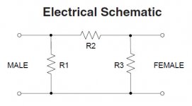
I'm pretty sure the resistors are there to create a 75Ohm impedance path, and to reduce the digital output level to the textbook 0.5mV... This has nothing to do with RF interference reduction (not to my limited knowledge anyway).
Also, I'm quite sure Peter wrote a while ago that he tried and didn't like RF attenuators (although I would wait for his confirmation on this). From memory, he never liked any "forced" forms of noise suppression, like power conditioning, chokes etc.
Personally, I'm a big believer in reducing RF interference by... moving devices that cause it away from your HiFi
In any case - if it works for you, then go for it, why wait for someone else's opinion?
Well, I am using them and have been for a while. Heres my original post (#4088
I'm just sharing my experience. FWIW, using these devices to drop from TTL is a far more precise way to do it than the 300/92 set.
Since the post above I removed those resistors and fitted a higher level attenuator. No much difference than having the 6dB one in place. But the difference between using them and not using them is large. Similar to the reclock circuit posted some time back, but maybe not quite as big a difference as that.
Hey - its worth trying out for the small ££ it costs!
Fran
OK, first up, don't shoot me ok? I'm not looking to derail this thread, or spark a believers vs non-believers argument that goes on for pages. I believe that has happened already on this (or the line level forum).
I have had cause recently to use some SPDIF attenuators between my shiga (fully modded, incl Peters reclock from some pages back) and my DAC. I still have the 300/92R on the TTL output to knock it down to consumer levels, but these attenuators are on top of that. What I have heard is a cleaning up of the sound similar to the reclock, but maybe not as large a difference. But for a few quid each, its well worth it I think.
Anyway, I post it here just because I've tried it in my system and like the effects. I would really like if a few more people tried it just to see. Much easier to try this than most of the other mods people have done here and the effect seem to be well worth it.
The attenuators are here:
http://minicircuits.com/pdfs/HAT-6-75.pdf
I use a 6dB one at either end of the SPDIF cable, but experiments of which level to use are to follow. Also removing the 300/92R completely and using these to knock down the TTL signal.
I'm just sharing my experience. FWIW, using these devices to drop from TTL is a far more precise way to do it than the 300/92 set.
Since the post above I removed those resistors and fitted a higher level attenuator. No much difference than having the 6dB one in place. But the difference between using them and not using them is large. Similar to the reclock circuit posted some time back, but maybe not quite as big a difference as that.
Hey - its worth trying out for the small ££ it costs!
Fran
FWIW, using these devices to drop from TTL is a far more precise way to do it than the 300/92 set.
Aren't those just resistors in a special package?
Attachments
Exactly! As a purist point of view, why should one add a resistor to ground in the signal path and also an additional connector?Aren't those just resistors in a special package?
If I can answer on Fran's behalf as I introduced them to him? Yes, Peter, they are BUT I guess they are precision resistors in a precision BNC case - 75ohm.
They certainly improve the sound of the Shigaclone even though there already is a T-Pad in there!
For Leopalour - the reason for using T-pads is to knock down the output voltage to within SPDIF. One side effect of doing this is that any reflections get knocked down by twice this attenuation which helps with a better signal. ( I won't use the word jitter reduction here to avoid controversy).
But again all I can say is that 7 people at Fran's were amazed by the effect these devices had on the sound
Last edited:
I just read jkeny's post and yours Peter.
The truth is, I don't know what's in there. Logic says there must be some resistors, but they could be filled with rocking horse sh!t for all I know. But I can tell you they make quite a difference. And Peter, as you and others who have been along this shiga road will know, the shiga is already a fine, fine sounding unit. This moves it up another notch.
And for not that much more than the price of the rikens (which you can dispense with and use the attenuators to knock the signal down from ttl).
Peter, I'm using them with a squeezebox into your NOS DAC and its really really nice. You should try 'em.....
Fran
EDIT: home made cable using 75R coax with BNC terminations and the other is 75R coax with RCA terminations and a BNC adaptor.
Something else I want to add.
These things are the subject of some controversy elsewhere, with circulating arguments etc.
Honestly, I hold no stock in these things, - I don't really care if the world is converted to them or not. But I heard (and others in my house, on 2 different systems with 2 different digital sources and different DACs + a friend who took one home to try out reports the same finding) a very positive improvement in sound - not just a difference, an improvement. These were not just people I pulled off the street, they were people whose ears I trust, but know nothing of DIY. It was not a controlled experiment, they knew I was doing "something" but not what it was. Most of them wouldn't know what a BNC connector was, never mind these attenuators. I just say all this to avoid some huge OT thread crapping - you can see I'm wary of this whole thing!
Just my 2c
Fran
Last edited:
- Home
- Source & Line
- Digital Source
- Finally, an affordable CD Transport: the Shigaclone story