Sure, it could be high jitter clock, but this is exactly how I wanted it. Check this link to see the reason why: GoodSoundClub - Romy the Cat's Audio Site - The clock upgrades: my proposals
On couple other occasions I also installed "jitter approved" high performance clocks and always went back to simple oscillator; it just sounded more natural.")
On couple other occasions I also installed "jitter approved" high performance clocks and always went back to simple oscillator; it just sounded more natural.
Sure, it could be high jitter clock, but this is exactly how I wanted it. Check this link to see the reason why: GoodSoundClub - Romy the Cat's Audio Site - The clock upgrades: my proposals
On couple other occasions I also installed "jitter approved" high performance clocks and always went back to simple oscillator; it just sounded more natural.
Interesting....
Bad day for the clock mongers. The crystal oscillator #810006 in the Mark Levinson is rather low jitter though.
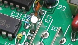
Romy's talking about modding CEC TL0, not Levinson, and it appears that TL0 uses very similar crystal to the Citizen I've been sugesting for Shigaclones, see attached pic.
The Citizen crystal is OK but it takes more making a low jitter oscillator.
Romy's double bass phenomenon is something I can't duplicate. I think Romy is telling fairy tales.
Hi,
I joined the forum some time ago because of this thread. With some difficulty, I managed to find a RC-EZ51. Until it is all sorted with power supplies and maybe some other mods it is mounted in some 18mm multiplex. The plan is to use separate power supplies of the board and the two motors, and maybe later add a Trichord clock with its own power supply.
Unfortunately, it seems I have already destroyed the digital out and therefore my project. I had mounted a pair of resistors of less-than-ideal values, and had not connected the shield of the 75 Ohm coax cable to the dac. While connecting the shield I swapped resistors for a 300/100 Ohm pair, and the solder pad for the digital output just let go. I have no experience with this kind of soldering, and probably overheated it.
Can anybody tell me if / how I can still get a digital output?
Thanks,
Jeroen
Last edited:
it seems I have already destroyed the digital out
You can get the signal from the IC (LC78601 pin29) or the track from the IC to the pad, but it's not an easy task. Are you sure the output pads cannot be repaired? Maybe you can remove the soldering with a desoldering sucker and use the pads again. Please post a photo.
I tried to post a picture, but cannot figure out how. According to the faq there is an 'albums and pictures' link in the user control panel. Except that there really isn't. What am I doing wrong here?
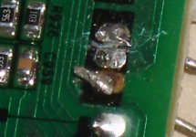
But back to the subject. All that is left of the pad is bare PCB. There is a very small chance that it is repairable though: I noticed a tiny spot of solder on the rear edge of were the pad used to be, right at were the PCB-track starts. So if I retract the resistor lead while heating it, the remaining solder might just flow and form a new pad.
However, I noticed that solder by itself does not really stick to a PCB. Can anyone tell me whether they glue the pads on, or is it really just a question of letting the solder flow at the right temperature?
I tried to post a picture, but cannot figure out how.
"Post reply"
"Manage Attachments"
Upload the image file and you can see it in the list
"Close this Window"
"Preview Post" and then, if ok, "Submit Reply".
Very easy.
I tried to post a picture, but cannot figure out how. According to the faq there is an 'albums and pictures' link in the user control panel. Except that there really isn't. What am I doing wrong here?
But back to the subject. All that is left of the pad is bare PCB. There is a very small chance that it is repairable though: I noticed a tiny spot of solder on the rear edge of were the pad used to be, right at were the PCB-track starts. So if I retract the resistor lead while heating it, the remaining solder might just flow and form a new pad.
However, I noticed that solder by itself does not really stick to a PCB. Can anyone tell me whether they glue the pads on, or is it really just a question of letting the solder flow at the right temperature?
No, you will need to scrape a little of the solder mask of off the end of the trace where you see the solder blob, and very carefully solder a small piece of kynar 30ga wirewrap wire to that trace. You can form a loop to replace the missing pad or just bring it directly through the existing hole. Once you are sure it is working ok secure it with a little super glue.
Do not solder the resistors directly to these pads, 30yrs of experience and I made the same exact mistake. (I'm fortunate to have several boards - so the one I damaged is now a back up.) Instead use short flexible wire (an inch or so will do) from the two board connections and solder the resistor pair to those. The boards are made of bottom of the barrel phenolic (paper based) and the traces are 1oz copper or less and the adhesive used to secure them is not that strong either.
Last edited:
Thanks for the great advice! I am practicing on the tuner PCB: removing the top layer to get at the traces (more difficult than I thought, usually I scratch straight through the trace as well), soldering on traces and solderpads to find the limits, etcetera.
BTW: Yesterday I was talking with my girlfriend about the queen's christmas speech, wherein she said that all these contacts in the virtual world lead to an impoverished social life. Well, I have a problem in the Netherlands, and people from the USA, Italy, Poland, and Canada have chimed in with advice. How much more social can you get?
So thank you all, and have a good 2010.
Jeroen
PS: here's a pic of the problem.
Attachments
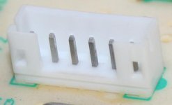
it's a standart problem. use a male plug. solder it sraight in position. Your's pad's will be safe. photo below shows the type of the nest. use 3 pin nest.
big drop of solder should keep this nest in proper position.
Check something different. Solder a 20R rezistor on the R957. You gonna love this mod.
big drop of solder should keep this nest in proper position.
Check something different. Solder a 20R rezistor on the R957. You gonna love this mod.
Attachments
Thanks for the great advice! I am practicing on the tuner PCB: removing the top layer to get at the traces (more difficult than I thought, usually I scratch straight through the trace as well), soldering on traces and solderpads to find the limits, etcetera.
BTW: Yesterday I was talking with my girlfriend about the queen's christmas speech, wherein she said that all these contacts in the virtual world lead to an impoverished social life. Well, I have a problem in the Netherlands, and people from the USA, Italy, Poland, and Canada have chimed in with advice. How much more social can you get?
So thank you all, and have a good 2010.
Jeroen
PS: here's a pic of the problem.
Have a nice 2010, Jeroen
And off course to all you guys on this forum.
Anton.
it's a standart problem. use a male plug. solder it sraight in position. Your's pad's will be safe. photo below shows the type of the nest. use 3 pin nest.
big drop of solder should keep this nest in proper position.
<snip>.
This is actually what I have done on both the damaged and undamaged pcb I have on hand. Works like a charm.. You may have a suitable connector that can be removed from one of the other boards.
Happy New Year to all!
Check something different. Solder a 20R rezistor on the R957. You gonna love this mod.
Sorry, Marosik, but could you be more precise. What do you mean by solder a resistor on the R957?
hmmm - R957 supplies +5v to the internal DAC - since I use my Shiga only as a transport and don't need the DAC, I've actually removed R957 to reduce the +5v load.
whatever a 20R resister does it is only going to affect the analogue outputs - shouldn't have any effect on the dig out.
whatever a 20R resister does it is only going to affect the analogue outputs - shouldn't have any effect on the dig out.
hmmm - R957 supplies +5v to the internal DAC - since I use my Shiga only as a transport and don't need the DAC, I've actually removed R957 to reduce the +5v load.
whatever a 20R resister does it is only going to affect the analogue outputs - shouldn't have any effect on the dig out.
Removing the power to the dac probably isn't such a great idea - all of the digital signals driving the dac portion of the IC are now driving unpowered ports which may have the effect of overloading them depending on whether the device is cmos or bipolar - you may in effect be increasing the current consumed by other parts of the IC whilst also degrading its performance. I would carefully consult the chip data sheet to see if this is OK. If they do not specifically mention this as an acceptable choice you should leave it powered.
Removing the power to the dac probably isn't such a great idea - all of the digital signals driving the dac portion of the IC are now driving unpowered ports which may have the effect of overloading them depending on whether the device is cmos or bipolar - you may in effect be increasing the current consumed by other parts of the IC whilst also degrading its performance. I would carefully consult the chip data sheet to see if this is OK. If they do not specifically mention this as an acceptable choice you should leave it powered.
I hear exactly what you're saying Kevin - I do have a full set of datasheets and refer to them regularly when experimenting on this board - unfortunately there is no specific mention of this on the DSP datasheet.
It has always seemed to me to be good practice to remove any 'unused' power users from any supply - although I must admit that the 'dead ends' that would remain inside the chip when I removed the DAC power was not something I had thought about

I actually removed R957 when I was clearing the board of the unecessary bits and perhaps got a bit carried away - In practice I don't think it has made any difference at all - positive or negative, but I like the idea of my supply going to the bits that use it and not the bits that don't ........ I may give it it's supply back next time the board is out for a mod and have a more critical listen!!
- Home
- Source & Line
- Digital Source
- Finally, an affordable CD Transport: the Shigaclone story