jitter said:
What voltage are you talking about (I don't see DC+ and DC- markings on my pcbs, I have the '51)?
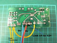
The mainboard gets 12 V from the rectify board. The mainboard makes 8 V out of the 12 V and feeds it to the CD-board (and also to other now unconnected boards).
Edit: the 8V output from the mainboard measures 8.6 V unloaded and 8.4 V loaded in my case.
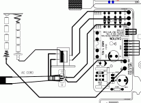
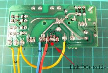
Ok, the rectifier board (BTW, there is a B+ pin there with a wire, close to the AC ins from the transformer: what is that B+ wire??).
Then, on the rectifier board, I have DC+ and DC- cables, that should go to the main board (the CD board, of course) connecting to +8V and GND, right?
This is the situation...
Kooka said:Ok, the rectifier board (BTW, there is a B+ pin there with a wire, close to the AC ins from the transformer: what is that B+ wire??).
The B+ is the wire from the battery compartment (via a switch on the power coard connection).
When there is no power cord in the boombox, it can run on batteries. When you plug the power cord in it disconnects the batteries (you can see a switch on top of the power cord connection).
Then, on the rectifier board, I have DC+ and DC- cables, that should go to the main board (the CD board, of course) connecting to +8V and GND, right?
This is the situation...
There are differences between the '31 and than the '51.
On the '51 boards are labeled:
- Rectifier Board
- Main Board (aka audio board)
- CD-board
- Casette Board
- Tuner Board
- Display Board
With "mainboard" I mean the board that some call "audio board".
The rectifier board connects to the main board only on the '51.
When looking at the schematics of the '31 I DC+, DC- and B+ are for battery operation. Don't measure the voltage there.
You only need to connect the rectifier board to the audio board and the audio board to the CD-board and display board (and of course the display board to the CD-board). That's it.
8V needs to be measured anywhere on the mainboard between 8V and GND (on the connector going to the CD-board these are CD-B+ resp. CDGND).
When you build your own 8 V power supply, you can throw away the rectifier board and audio board.
Attachments
Kooka said:Just disassembled my boombox, and from its own psu I test (no load) 13vdc (on dc+ dc- pins), is it normal..? Can I feed the board with those values?
Attachments
Thanks.
But you see this, for example: there is no "audio board" or anything. There's only a transformer, the rectifying board and the cd board, and that's all. Now my problem is that from the rectifier board I donìt get more than 1,5V now
What the hell...
But you see this, for example: there is no "audio board" or anything. There's only a transformer, the rectifying board and the cd board, and that's all. Now my problem is that from the rectifier board I donìt get more than 1,5V now
What the hell...
Attachments
audio1st said:
Anyway in this way I still get (no load) 14V fromthe 2 pins that were supposed to give 8V... I still think it is too much. I wander what's wrong with this stock psu

Kooka said:Thanks.
But you see this, for example: there is no "audio board" or anything. There's only a transformer, the rectifying board and the cd board, and that's all. Now my problem is that from the rectifier board I donìt get more than 1,5V now
What the hell...
My mistake! All the time I overlooked the fact that the circuit that makes 8V is on the rectifier/power board in a '31
! In my '51 it's on the main/audio board. They actually have the same reference designators (Q401, D401, etc.), though...Next time I'll ask which model the question is about first.
jitter said:
My mistake! All the time I overlooked the fact that the circuit that makes 8V is actually on the rectifier board in a '31
Next time I'll ask which model the question is about first.
Well, thanks anyway bro, that was appreciated anyway. And I think I solved the situation, now... 11,5V with no load from the 8V pins: I guess it starts being ok.
Kooka said:
Well, thanks anyway bro, that was appreciated anyway. And I think I solved the situation, now... 11,5V with no load from the 8V pins: I guess it starts being ok.
thinks 11.5v sounds to high, trye to conect it to an load and see how mutch it drops befor you connect it to the player
Still on the high side...
Do you have some resistors lying around? Maybe you can load the 8V up starting with 470 ohms and then down in steps. See if the output drops towards 8V more and more if you lower the load-resistance.
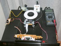
I measured with a clamp amp meter (very inaccurate at these low currents) on the 8V wire going to the CD-board. With a CD playing it seems to draw around 0.2 A.
Edit: valo and audio1st were a bit quicker...
Do you have some resistors lying around? Maybe you can load the 8V up starting with 470 ohms and then down in steps. See if the output drops towards 8V more and more if you lower the load-resistance.
I measured with a clamp amp meter (very inaccurate at these low currents) on the 8V wire going to the CD-board. With a CD playing it seems to draw around 0.2 A.
Edit: valo and audio1st were a bit quicker...
A quick question for Audio1st
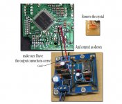
I did see in somewher in this thread that you did use the "red" ebayclock, but is i can remeber youre clock was a litle modyfied, guess you have removed the bridge so that you may run it on DC rigth ?
And did you connect it like its done in this picture ??
I did see in somewher in this thread that you did use the "red" ebayclock, but is i can remeber youre clock was a litle modyfied, guess you have removed the bridge so that you may run it on DC rigth ?
And did you connect it like its done in this picture ??
Ok, it worked: just connected the B+ wire to DC+ and not with the 12V+.
Now the problem is ... I burned the led (too little dimming resistor) I have to put the display under a smoked lens so I tried feeding it with 8V and it was too juch with a 1k resistor there (5,6K was working but too much dimmed).
Anyone knows how to reach the led without destroying the display itself, guys?
Kooka said:Ok, it worked: just connected the B+ wire to DC+ and not with the 12V+.
Now the problem is ... I burned the led (too little dimming resistor) I have to put the display under a smoked lens so I tried feeding it with 8V and it was too juch with a 1k resistor there (5,6K was working but too much dimmed).
Anyone knows how to reach the led without destroying the display itself, guys?
Use a 5k potmeter then you have a dimmer.. and when your happy whit the ligth measure the potmeter and replace it whit an resistor
valo said:A quick question for Audio1st
I did see in somewher in this thread that you did use the "red" ebayclock, but is i can remeber youre clock was a litle modyfied, guess you have removed the bridge so that you may run it on DC rigth ?
And did you connect it like its done in this picture ??
Hi, yes I removed the bridge and powered it from the DC before the 7808 (about 17V). I also had to change the gold cap on the clock board because it only had a 16V rating. Only a single connection to the crystal location (XO), because it shares the same power supply ground.
Attachments
Re: Re: Re: Re: Another clone rears it's ugly drive!
It has been and thank you Kevin for reminding me of this. I'll report back once I've put in the proper network.
I have high hopes for the AOB/cMP-Squared-type 'hair-shirt' music player that I'm currently sourcing & starting to assemble , but I'm getting my TT setup up & running again notwithstanding.
Thanks for the tip on the downloads too!
I was very reminded of that last night. I decided my Shiga was sounding a bit emphasized in the upper midrange / lower treble and decided to try a few things to mellow it out:
1. Damping material on the clamp... no, sounded a bit confused (but the damping wasn't as well-centered and balanced as I wanted... may have to try this again later and do it better).
2. Change mounting screws from original stainless steel to brass... Yup, that moved it in the right direction, but now it's a bit too warm and too much detail is lost.
3. Change one of the mounting screws (the one farthest away from the CD spindle) back to stainless... yup, this moved it to a good middle-ground.
4. Swap the screws' positions... nope, a little too emphasized again.
I put the screws back to the #3 configuration.
I was mildly surprised that it was this sensitive!
Greg in Mississippi
kevinkr said:No, it's not short enough and never will be simply because the cable is not correctly terminated into its characteristic impedance at the sending end.<SNIP>(I think I have already mentioned these issues a few times in this thread.)
It has been and thank you Kevin for reminding me of this. I'll report back once I've put in the proper network.
FWIW I think the Shigaclone is great, and in my system it offers the most natural sounding CD playback I have yet experienced, that said it REALLY pales in comparison to good analog (R2R tape or LP) or SACD. I have also downloaded live pcm recordings of admittedly pretty obscure bands from www.archive.org with 24 bit 48K or 96K sample rates and these easily better my best CDs for sound quality in many instances as well. (Media server required, and files are flac format.) Might as well get the best from your CD collection possible, but don't fall into the trap of thinking that CD offers anything close to the best achievable audio performance - it clearly doesn't and can't.
I have high hopes for the AOB/cMP-Squared-type 'hair-shirt' music player that I'm currently sourcing & starting to assemble , but I'm getting my TT setup up & running again notwithstanding.
Thanks for the tip on the downloads too!
The mounting technique was very audible as Peter said and the additional mass helped as well.
I was very reminded of that last night. I decided my Shiga was sounding a bit emphasized in the upper midrange / lower treble and decided to try a few things to mellow it out:
1. Damping material on the clamp... no, sounded a bit confused (but the damping wasn't as well-centered and balanced as I wanted... may have to try this again later and do it better).
2. Change mounting screws from original stainless steel to brass... Yup, that moved it in the right direction, but now it's a bit too warm and too much detail is lost.
3. Change one of the mounting screws (the one farthest away from the CD spindle) back to stainless... yup, this moved it to a good middle-ground.
4. Swap the screws' positions... nope, a little too emphasized again.
I put the screws back to the #3 configuration.
I was mildly surprised that it was this sensitive!
Greg in Mississippi
Peter Daniel said:C952 is removed (as well as the L901 choke), C916 is replaced by BG N 47/50; corresponding ceramic bypasses are also removed.
I added BG N 4.7/50 in parallel with first BG STD in regulator circuit, as the sound was a bit too "abrassive" for my taste.
This is how it looks after all is done.
Peter talks about "ceramic bypasses", but actually I found only ONE ceramic bypass (marked "4" in the pcb underside in the PDF).
No other "ceramic bypasses" (plural) found there between C952 and C916.
Or am I missing something? Was Peter talking about other "ceramic bypasses" at that point?
- Home
- Source & Line
- Digital Source
- Finally, an affordable CD Transport: the Shigaclone story