 This is a complete turnabout...
Peter Daniel said:I wouldn't be loosing sleep over all those additional mods and finding Black Gates.
I just put together another transport, the mechanism is mounted on standoffs to a bottom copper plate.
I only replaced PS, as descibed here: http://www.diyaudio.com/forums/showthread.php?postid=1468036#post1468036
Everything else, including resonator, is stock. The output resistors are 100/300R Mills.
The transport plays really good, as good as the original Shigaraki.
In some ways it is better that my prevous built, especially when it comes to raw energy in reproduced sound. The trade off is slightly less refinement and smoothness, but when you get used to it, you won't even notice
I will later post more pics of the inside job.
Nice sharp lines to your Shigaclone BTW

SCD said:
How about a few more pictures
While Eric pushes here the envelope of State of the Art, I tried to come with a simple solution that averybody can follow.
Let's start with PS. I used a circuit described here: http://www.diyaudio.com/forums/showthread.php?postid=1468036#post1468036
48VA Hammond transformer fits perfectly in a Hammond 1590T enclosure:
An externally hosted image should be here but it was not working when we last tested it.
Diodes are mounted directly to connector socket:
An externally hosted image should be here but it was not working when we last tested it.
and the whole thing came out quite elegant:
An externally hosted image should be here but it was not working when we last tested it.
I was debating for days how to make it simple, yet nice looking. In the end I decided on a wooden frame mounted between two panels: frosted acrylic on top and copper on a bottom:
An externally hosted image should be here but it was not working when we last tested it.
An externally hosted image should be here but it was not working when we last tested it.
An externally hosted image should be here but it was not working when we last tested it.
The PS is made on protoboard with 2 x BG STD 1000/25 caps. LM7808 regulator is attached directly to bottom panel. Two oversized brass standoffs support the mechanism:
Control switches are recycled from the original boombox; I used standoffs and protoboard to mount them:
I also implemented the original display board, slightly modyfing it to fit inside the chassis:
An externally hosted image should be here but it was not working when we last tested it.
Control switches are recycled from the original boombox; I used standoffs and protoboard to mount them:
An externally hosted image should be here but it was not working when we last tested it.
I also implemented the original display board, slightly modyfing it to fit inside the chassis:
An externally hosted image should be here but it was not working when we last tested it.
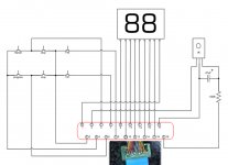
Pictures below show modifications to a display board: it's been trimmed, and where important traces had to be cut, they've been replaced with hookup wire.
Unneccessary components in top layer were removed:
There are 5 connection points to the switches:
2 common for all switches
S stop
P play
B back skip
F forward skip:
An externally hosted image should be here but it was not working when we last tested it.
Unneccessary components in top layer were removed:
An externally hosted image should be here but it was not working when we last tested it.
There are 5 connection points to the switches:
2 common for all switches
S stop
P play
B back skip
F forward skip:
An externally hosted image should be here but it was not working when we last tested it.

Now, how does it sound? It sounds pretty damn good and I don't really feel tempted to touch anything, except maybe for trying the oscillator.
It has that raw energy that impressed me so much when I listened first time to Shigaraki; it's a bit less smooth and refined than my other clone, but for now it doesn't bother me at all
It has that raw energy that impressed me so much when I listened first time to Shigaraki; it's a bit less smooth and refined than my other clone, but for now it doesn't bother me at all
Hello Gang. I am jumping back in after taking the summer off. before putting it away last spring I did manage to get all the mods done to the power supply and drive boards. I had a one off cast made out of aluminum with 1/2" sides and bottom for the chassis. I am now trying to figure out how to do the display and function buttons. Quick question. I know the lid switch needs to be a on/off, but I am not sure about the function keys? Are they on/off or momentary?
Peter, thats just beautiful work. Very zen, very 47 labs!
I have a second one of these to start putting together and I think I'm going to do something very similar to what you have there.
Question about the puch buttons...... I understand you using the original buttons from the PCB. What do you do then - is it just a case of machining a few from solid bar so that they rest on top of the original buttons when the top is on? Do they feel good in use, or is there any problems with them rattling or anything in use?
Some more pics (sorry a pain I know) of how you did the buttons would be most helpful.....
Fran
I used the same idea as here: http://www.diyaudio.com/forums/showthread.php?postid=386057#post386057
Cylindrical push buttons are attached to microswitches with double sided adhesive tape, works great. The holes in acrylic panel need to be only slightly bigger than the buttons, for smooth action.
I didn't finish that part yet, also I made mistake with TOC switch, the one from boombox can't be used as it needs to be normally closed.
valo said:Peter you did write that you did not like "toroide" transformers in digital circuts , but i dident understand why.. iam using an toroide
I'm not sure if they better, but it's quite common to use split bobbin transformers with digital or low power electronics in general as they provide better separation from AC line.
Badge said:I am now trying to figure out how to do the display and function buttons. Quick question. I know the lid switch needs to be a on/off, but I am not sure about the function keys? Are they on/off or momentary?
Display schematic attached. All switches are momentary: normally closed for lid and normally open for other functions.
Attachments
- Home
- Source & Line
- Digital Source
- Finally, an affordable CD Transport: the Shigaclone story