Thanks, I connected it like this, but with some cd`s (atm only 1 cd is readable) he hits his end stop, and somehow doesn`t spin up to full speed either...kevinkr said:The crystal is soldered to the outer holes, the center hole is ground and is not used with the crystal. (The resonator had internal caps connected to this point.)

I`m going to try to attach some caps. What would be a good value?
Hello I have the crystal clock (trichord) with powersupply mounted with 2 wires and no capacitors and working....did you check all the other stuff eg. ...the toc switch....because that is a very weak plastic thingie...
I am suggesting this because you have a cd that gets read..

Anyway my real reason for posting:
GET RID OF THE MAGNET...
Using the Acryl or Delrin Platform and screw puck might be a bit of a hassle in the first place but in my set-up and in my perception it is nearly as "huge" as an expensive clock with powersupply and superregulation...
After loads of cd's I played since starting this project I became cd after cd rock steady convinced
Instruments and voices become much more
"recordplayer-like"...a virtue I have no clue to reach otherwise with digital.....
I am suggesting this because you have a cd that gets read..
Anyway my real reason for posting:
GET RID OF THE MAGNET...
Using the Acryl or Delrin Platform and screw puck might be a bit of a hassle in the first place but in my set-up and in my perception it is nearly as "huge" as an expensive clock with powersupply and superregulation...
After loads of cd's I played since starting this project I became cd after cd rock steady convinced
Instruments and voices become much more
"recordplayer-like"...a virtue I have no clue to reach otherwise with digital.....
Thanks for the reply Erik, I checked the doorswitch and its ok.
I tried spinning my clone without a cd, and it does exactly what it does when "reading" a cd:
- Spin up cd ( imho not wel up to speed and slow roll on!!)
- Move laser assambly 1 mm to the left ( it hits his end position after reading)
- Focus the laser (only goes max in, and max out, with no obvious trace of focus.)
- Call "00 / no cd
This is exactly what it does, either with, or without a cd...
I tried all variations on the caps, resonators and such now. Same with the added twisted wires.
To me it seems the laser isnt reading anything (perhaps because the cd isnt up to full speed? ) It just follows the same routine focus everytime.
I checked my PS, for voltage which was a steady 8.02 volt. I`m going to change the diodes now perhaps one is broken and its not reaching into his max current? I`m using msr860`s x2 btw.
Pff, this will be some trouble shoot ;-)
* edit: good point Erik, but no cd`s get read anymore now arg
I am not quite sure if it's just a magnet. I think the mass of a new table mounted on a whole length of a shaft may have something to do here as well.
Changing discs is not really a hassle for me, when approched properly, the process can become very simple.
And yes, that upgrade is much recommended; it is also my impression that the effect can be compared to adding a dedicated clock, as I already mentioned previously.
Changing discs is not really a hassle for me, when approched properly, the process can become very simple.
And yes, that upgrade is much recommended; it is also my impression that the effect can be compared to adding a dedicated clock, as I already mentioned previously.
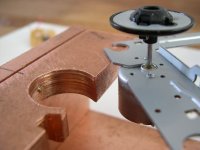
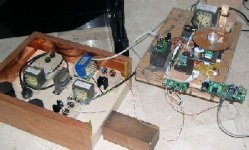
Okay another "mistake"....
The ring for the motor is not a succes ...the screws to position him opened up the ring...and height together with a perfect 90 degrees seems nearly impossible to get....to much deviation...
I seem to have found a better solution...
Out of a billet copper 12 mm I made a mounting hole nearly covering up the hole motor-encasing...
This time only ONE screw to adjust the height..
It is still possible to detach the motor by lowering it 1.5 mm and attaching the board not to the copper but underneath a strip ebony....by only drilling 2 holes through the copper...
A lot of work so far but I think this is an important bit....
BTW the filed bit next to the motorhole is for the toc-switch...I had to change that as well cause of the new construction...
Attachments
About my oscilator problem:
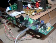
There was a small piece of cut-wire inside the laser compartment... I normaly don`t clean up my workspace, but I will from now on!
I had a spare one, so when putting all the parts on the "new" one, I came across that little wire that was obstructing the laser from moving properly.
Glad thats fixed -although kinda stupid.. -
How do you guys handle your mechanism when modifying?
I`ll install the crystal tomorrow, see how it goes. Atm, I`m happy I have my clone up and running again.
Thanks for all the crystal replies and help.
There was a small piece of cut-wire inside the laser compartment...
I normaly don`t clean up my workspace, but I will from now on!I had a spare one, so when putting all the parts on the "new" one, I came across that little wire that was obstructing the laser from moving properly.
Glad thats fixed -although kinda stupid.. -
How do you guys handle your mechanism when modifying?
I`ll install the crystal tomorrow, see how it goes. Atm, I`m happy I have my clone up and running again.
Thanks for all the crystal replies and help.
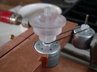
Erik van Voorst said:Obviously this is not gonna work yet..but the way the motor is mounted in my 2nd "test-set-up" takes me further for new ideas.
...........................brainstorming...........
Erik, i really think this idea has a enormous potential. it has convinced me to spend some time figuring out how to get a 2mm shaft mounted on a bearing.
rikkert1978 said:About my oscilator problem:
There was a small piece of cut-wire inside the laser compartment...
I had a spare one, so when putting all the parts on the "new" one, I came across that little wire that was obstructing the laser from moving properly.
Glad thats fixed -although kinda stupid.. -
How do you guys handle your mechanism when modifying?
<snip>
Very carefully... You do know that these are static sensitive? I keep the area I am working in scrupulously clean and use an anti-static strap and grounding system.. I specified a low esd treatment on my bench top when I ordered the bench - although by now it's old enough that I would not count on it. A grounded anti-static mat would be even better.
Foreign objects in or around the laser assembly are bad news, you got very lucky..
okapi said:
Erik, i really think this idea has a enormous potential. it has convinced me to spend some time figuring out how to get a 2mm shaft mounted on a bearing.
Please inform me if you make progression I find that getting the proper ideas is one thing but finding the right materials is an other....

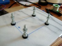
Maybe that picture gives you some ideas ")
An externally hosted image should be here but it was not working when we last tested it.
Hi
I am folowing the thread form the beguining...
extremly interesting
I tryed the transport with no modifications,
and poor, reconnected, self power supply
with a dac inside...
(now I am without the DAC, so I could not try the SPDIF out...)
the transport sounds not bad at all,
even with the inproper audio out components values:
Power supply is common
should be sepparate:
remove R957(220ohm)
and put the 5V analog PS...
C964 and C945=3.3uF should be minimum 10uF
R961 and R960=5.6K that is wrong value, because of most solid state amps or preamps
have 10K input R, parraleling with 5.6K is too low and leeds to bigger value
of min. 47uF which is too high value for find good one, and phase shift C is bigger
leeds to ugly bass... tube equipment, on the oter hand, have higher values of pots and Rin...
in booth casses, R961 and R960 should be higher a 100k min.
probably we have an oversampling in the system internal chip...
So the C948 and C947 are not propper filtering
even in conjunction of about 100pF-150pF added cable capacitance...
I suggest to remove them.
Expetially for those who using tube amps, because the most OT are not capable to transfer the highs beyond the 40KHz
or do the proper one...
R955 and R956 are the good ones they protect internal OP amp from short circuit conn.
*
I tested all that with borrowed, louzy tube amp assembled from 2 old tube radios
my oppinion that bandwitht is 120Hz-12KHz -3db
and old Lowther Acousta deluxe cabinets
which are from approximatly same bandwith...
the amp has high D-factor, and huge phase shift in lower end
so the bass is misty...
But middle is not bad at all
*
I am positive that with the SPDIF would be
as You guys already tryed...
thanks
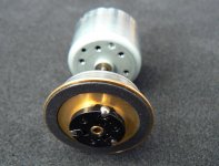
Here some additional info regarding disc table as posted on 47Labs site: http://sakurasystems.com/articles/pitracermemo.html
3. Platter
The platter is machined out of acrylic. Only the inner clamping area and the outer edge touches the disc. The disc would be clamped down at the center by an acrylic clamper. This makes the disc flattened out except the unevenness of the thickness of the disc itself. You can see the effect of this system by looking at the reflecting image on the rotating disc surface with which you won't be able to tell whether it's moving or not.
The reason I made the platter and the locking clamper by acrylic is to minimize the unnecessary inertia, to eliminate magnetic effect on the actuator coil, and most importantly, after the motor is fixed to the platform and the acrylic platter is pressured in, we can re-machine each platter one by one while it's rotating to ensure the flat plane of the surface. By this method, the aforementioned flickering of an image on the rotating disc is further minimized.
I have got around 3000 cd's......in order to tell if a disc is rotating or not he must have picked the one without flaws......happy searching......... 
Anyway yesterday we made again quite a huge leap by getting rid of the SPDIF...
I am able to do that since my Genesis Digital lens has an AT&T Input......
We installed a (Wadia) board with AT&T...gave it a dedicated power supply with the edition of a 5V ALWSR board hooked it up with the Lens.....and were again very pleasantly surprised...
We silently hoped for the same shocking results as the AT&T did with the Wadia (a couple of weeks ago) in an
SPDIF shoot-out and were not disappointed...
The complete Analog sound stayed the same but more body....more resolution...more definition in the lows...(leaving the mids alone !!!)...
A win win situation ....this boards stays in...
The comparison is maybe a bit like driving a Corvette with a small block and modifying it with a big block....
Attachments
Erik van Voorst said:I need a bigger boat....
I'd say it's taking on a life of its own..
I'm going to look for a cdrom ball clamp at some point..
- Home
- Source & Line
- Digital Source
- Finally, an affordable CD Transport: the Shigaclone story