Re: CD Clamp
Search Clearaudio (Roy) in this thread, if you wish.
Cheers
Pocoyo said:Is Okapi selling his clamp Now ?
Regards, Jeffry
Search Clearaudio (Roy) in this thread, if you wish.
Cheers
I agree with Kevin stick to the magnetic puck, at least until something better comes along. I have been trying to stop mine from wobbling, using Peter's method, for the past 2 days. It is not much better. I am taking mine to a machine shop on monday to see if they have any ideas.
JimS
JimS
jims said:I agree with Kevin stick to the magnetic puck, at least until something better comes along. I have been trying to stop mine from wobbling, using Peter's method, for the past 2 days. It is not much better. I am taking mine to a machine shop on monday to see if they have any ideas.
JimS
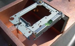
Mine had wobble in two planes and while I could have shaved the platter to get rid of the vertical wobble, the eccentricity in the horizontal plane would have remained. My mechanism could not even read the tocs with the original or much improved clamp mechanism.
Loading and unloading cds was really difficult as well, getting the clamp tight was hard, and getting it loose afterwards was if anything even more difficult..
It looked cool, but the idea is not such a hot one unfortunately. A small weight based set up like that used in some high end Sonys would work better at the possible risk of knackering the lower motor bearing.
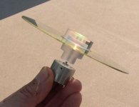
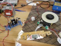
...today I picked up clamp no. 1000 
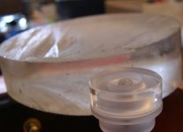
I definately want to get rid off the magnet so I am willing to go thru Hell....and believe me I am....this time from a pro shop...made out of a big chunk of acryl....
Anyway this one seems to be the best so far..it gives a rather good alignment..
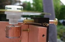
At the same time I kind-off over engineerd a brake system so I won't have to touch the cd's while handling the puck....you do not want that a very uncomfortable job...
I definately want to get rid off the magnet so I am willing to go thru Hell....and believe me I am....this time from a pro shop...made out of a big chunk of acryl....
Anyway this one seems to be the best so far..it gives a rather good alignment..
At the same time I kind-off over engineerd a brake system so I won't have to touch the cd's while handling the puck....you do not want that a very uncomfortable job...
Attachments
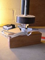
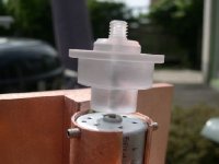
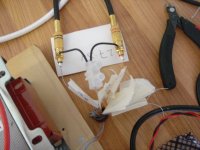
I pressed it home with a drillchuck....using its wheel and some helpfull handmade tools..( wooden clamp en a wooden platform with holes to support the bottom of the motor as "stressfree" as possible........
for me 2.5 mm space from the bearing does the job
(1 mm standard and 1.5 mm for detachment)
for me 2.5 mm space from the bearing does the job
(1 mm standard and 1.5 mm for detachment)
Attachments
BGF 4.7uf 50v
Hiii
Theres BGF Capacitor BGF 4.7 uf @ US$ 4.5 each
if someone want to try this i can help anyone
who want to buy this replace BGN 4.7uf 50v
For posted everywhere for mail cost max US$ 2.5
for 10 pcs and registered pos US$3.5 safely
Oh yes i still have BGF 470uf 35v @ US$ 10 each
and the bigger voltage BGF 470uf 50v @ US$ 10 each
you can make serial to have 1000uf
Mail cost for 470uf need address confirmation first
regards, jeffry
Hi
I have just connected everything up for the first time and it all appears to function correctly...
I don't currently have an external DAC and want to connect a couple of RCAs to the on-board DAC.
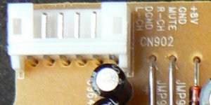
The cables coming from the on-board DAC are labelled
CD-L
CD-R
CD-GND
Mute
CD-B+
D-GND
Do I connect the both CD-L & CD-R to separate RCAs and connect the CD-GND to both ground tags on the RCAs?
A bit of daft question, I know
Thanks
Richard
I have just connected everything up for the first time and it all appears to function correctly...
I don't currently have an external DAC and want to connect a couple of RCAs to the on-board DAC.
The cables coming from the on-board DAC are labelled
CD-L
CD-R
CD-GND
Mute
CD-B+
D-GND
Do I connect the both CD-L & CD-R to separate RCAs and connect the CD-GND to both ground tags on the RCAs?
A bit of daft question, I know
Thanks
Richard
Attachments
Tripmaster said:Do I connect the both CD-L & CD-R to separate RCAs and connect the CD-GND to both ground tags on the RCAs?
That's exactly what you need to do.
Zigis said:Fantastic job, Erik!
Brake system is really great idea, however motor spindle is tiny and in long use motor may don't like power from one side.
Maybe in your super system better try something like bicycle break, symmetrical power from two sides?
Zigis
Yes I am busy to perfect it with some sort of lock...(eg. pin in hole...so no power at all on the spindle) but I want to wait a while before I start carving in the plug....it needs furthermore experimenting....
Tripmaster said:Hi
I have just connected everything up for the first time and it all appears to function correctly...
I don't currently have an external DAC and want to connect a couple of RCAs to the on-board DAC.
The cables coming from the on-board DAC are labelled
CD-L
CD-R
CD-GND
Mute
CD-B+
D-GND
Do I connect the both CD-L & CD-R to separate RCAs and connect the CD-GND to both ground tags on the RCAs?
A bit of daft question, I know
Thanks
Richard
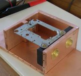
Hi Richard, the audio gnd is the wire next to the orange wire. Is this what you have used?
I see you have gone for the 100VA tranny
Attachments
audio1st said:
Hi Richard, the audio gnd is the wire next to the orange wire. Is this what you have used?
I see you have gone for the 100VA tranny
Hi Audio1st
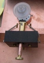
I was using the other ground connection. I have swapped to this ground and the hum has gone but I still don't have any sound.
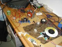
This is what I have completed so far.
Lower PCB
Have removed all of the SMDs, soldered wire to the digital out solder pads and terminated with RCA. (Not using at the moment as I have no external DAC)
I have not connected the jumper lead.
Upper PCB
Removed the choke, and the following caps as per the PDF
R1,R2,R5 - I have left R3 (DAC Bypass) in
I have not upgraded any of the capacitors with BGs yet.
Richard
p.s The 100va was only a few £s extra so I thought what the hell
Attachments
- Home
- Source & Line
- Digital Source
- Finally, an affordable CD Transport: the Shigaclone story