I tried again with the 5V supply, this time connecting it to point 5A on the pdf. I cut the trace that goes between that point and the cap near to the inductor. But still no luck - the disc continued to spin without reading the TOC.
On wiring 5A to 5B and reverting to just the 8V supply normal operation returned.
What am I doing wrong - any ideas?
On wiring 5A to 5B and reverting to just the 8V supply normal operation returned.
What am I doing wrong - any ideas?
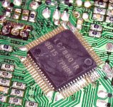
Suggested a while back, but there are reset lines in the driver chip that my need the transistor in the regulator circuit in order to function correctly. If you have a scope, you might look at those two lines to see if they behave the same with the differing power situations.
Pins 16 and 17 on the LA6541.
Pins 16 and 17 on the LA6541.
jonners said:
Hi Richard
I got my caps from Parts Connexion. Filling in their order form was a bit tedious but delivery was extremely fast.
Don't think you've missed anything.
John
Thanks John
I was going to try ordering through Percy Audio (not sure how speedy their service is) and get the remaining parts from Peter.
I am new to electronics, so can you answer this? If a suggested capacitor is for example 4.7/50v, will a 4.7/100v be OK as a substitute? I am assuming the voltage is a maximum and does not affect the sound.
Richard
In general substituting higher voltage caps is ok, however physically they may not fit the available space. (In the old days it was recommended that much higher voltage rated caps than called for in a particular application not be used due to deterioration in the dielectric at lower than design voltages, causing a reduction in capacitance, etc.. - this no longer appears to be a problem with modern caps, and today generally the higher voltage rated parts have better DA/DF performance than comparable lower voltage parts.)
I have been dealing with Michael Percy for over 20yrs now and he is both prompt and reliable.
On an unrelated topic make sure that the platter and clamp assembly on your 'clone runs flat and true as the increase servo activity if this is not the case seems to ruin the sound. I have one platter that is nearly perfectly flat and one that isn't and I thought I could hear a definite difference. Should yours not run true find one off of an old laptop cdrom drive as discussed earlier in the thread.
kevinkr said:In general substituting higher voltage caps is ok, however physically they may not fit the available space. (In the old days it was recommended that much higher voltage rated caps than called for in a particular application not be used due to deterioration in the dielectric at lower than design voltages, causing a reduction in capacitance, etc.. - this no longer appears to be a problem with modern caps, and today generally the higher voltage rated parts have better DA/DF performance than comparable lower voltage parts.)
I have been dealing with Michael Percy for over 20yrs now and he is both prompt and reliable.
On an unrelated topic make sure that the platter and clamp assembly on your 'clone runs flat and true as the increase servo activity if this is not the case seems to ruin the sound. I have one platter that is nearly perfectly flat and one that isn't and I thought I could hear a definite difference. Should yours not run true find one off of an old laptop cdrom drive as discussed earlier in the thread.
Thanks Kevin for the information. You might know this, The cap is the 4.7/50v. Will the 100v cap fit in it location? There is only 3mm in it so I guess it will. The legs should also be the same distance apart
Richard
hayenc said:Suggested a while back, but there are reset lines in the driver chip that my need the transistor in the regulator circuit in order to function correctly. If you have a scope, you might look at those two lines to see if they behave the same with the differing power situations.
Pins 16 and 17 on the LA6541.
I remember seeing your idea and I left the transistor in the regulator circuit, so that should still be functioning. Thanks for your suggestion, though. I don't have a scope but I will see if I can find a way of understanding what's going on.
jonners said:
I remember seeing your idea and I left the transistor in the regulator circuit, so that should still be functioning. Thanks for your suggestion, though. I don't have a scope but I will see if I can find a way of understanding what's going on.
Perhaps this is why Peter cut the trace and fed +5v from C916 on. Leaving the transistor in place may serve some function I'm overlooking.
Regards,
Dan
johnm said:Finally finished with the electronics side of the Shigaclone now - at last!
VERY happy indeed with it - certainly the best sound from red-book CD I have heard to date... and its still sitting bare on an upturned mouse mat haha! Will be experimenting with bamboo chopping boards next!
Altered my DPA DAC to BNC inputs this afternoon, and changed the output on my Shigaclone to BNC also. Also changed the output resistors to 392 /93 ohms yesterday. I'm amazed at the change - punchy bass which you can sometimes feel rather than hear. Nice 'bouncy' bass guitar rendition which one is able to follow, rather than having it submerged as in lesser players. All the sound quality of the stock JVC now, but with added punch, detail, and refinement (but NOT at the expense of speed or an exciting sound). Love it! Have to say though I also had more or less the same quality from using that resistor output with regular phono sockets as well. Adding the BNC's didn't seem to improve anything, at least not that its really noticeable - perhaps a little extra clarity but hard to tell.
I have to say that I am currently not missing my Garrard 401 rig at all, which is saying something!
Incase nobody can be bothered to read through the posts, here's a summary of what I changed:
C934 - 4.7uF Black Gate N
C929 - 4.7uF Black Gate N
C953 - 47uF Black Gate N
C906 - Keep the original in place!!!
C916 - 47uF Black Gate N
C939 - 47uF Black Gate N
C952 - 470uF Elna Silmic ARS
X901 - Citizen CSA-309
Remove - refer to Okapi's PDF file.
Digital output - 75-ohm BNC. 392 ohms series, 93 ohms shunt.
- John
Hi John
I think it pays to read a few more posts prior to asking unnecessary questions!
Regards
Richard
Zigis said:Citizen 300-8441 crystal frequency is 16.9344Mhz, I can find locally only quartz 16.0000Mhz.
Can it work ?
Zigis.
nope .
rene123 said:With the chance of facing a stone wall again...
Annyone able to provide a datasheet of the LC78601R?
Been looking for a while but somehow i can't seem to open the sheet.
(No MS office)
So a PDF will do.
Thanx, René
LC78601R or LC78601E ?
I have E
")
send me a mail and I'll send you pdf

rene123 said:With the chance of facing a stone wall again...
Annyone able to provide a datasheet of the LC78601R?
Been looking for a while but somehow i can't seem to open the sheet.
(No MS office)
So a PDF will do.
Thanx, René
Here's the 'E' online
LC78601E
Regards,
Dan
A little clarification please regarding digital output from the transport. I've read this thread at least 3 times but I'm still a bit confused.
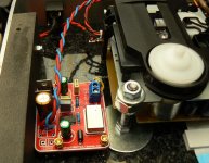
I see from Peter's pictures that he took D-out from the opposite side of the pcb from where D-out is shown over by the TOC switch. I assume this is because of the hole that he drilled to get direct access to the pin. Are most folks using D-out for the location of the voltage divider?
I see from Peter's pictures that he took D-out from the opposite side of the pcb from where D-out is shown over by the TOC switch. I assume this is because of the hole that he drilled to get direct access to the pin. Are most folks using D-out for the location of the voltage divider?
Hi Audio1st...
How did you go about...mounting the clamp..
Pitty you did 2 mods at the same time...anyway I guess both for the better...
I am still awaiting my 2nd clamp (first one was off-center) and am planning to try to mount it without force.....
Did you measure in some sort of way...
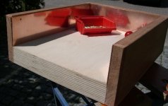
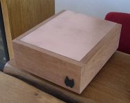
Today I finished the sides and the top of the piTbull psu-box..
I used 2 mm copper.....
And hey my regulators arrived today....heating up...
How did you go about...mounting the clamp..
Pitty you did 2 mods at the same time...anyway I guess both for the better...
I am still awaiting my 2nd clamp (first one was off-center) and am planning to try to mount it without force.....
Did you measure in some sort of way...
Today I finished the sides and the top of the piTbull psu-box..
I used 2 mm copper.....
And hey my regulators arrived today....heating up...
Attachments
- Home
- Source & Line
- Digital Source
- Finally, an affordable CD Transport: the Shigaclone story