
dantwomey said:
The ALWSR replaces the LM7808 shown on the diagram on the first page of this thread.
The shortcoming of that is that you won't get the full advantage of the ALSWR because the supply is still going through the internal 5V regulator in the LA6541 chip. (That's according to the schematic -which Erik says is incorrect. Post 1269 refers to MM1469. The chip is under the heatsink so the number is not visible.)
brgds said:could you advise in details how to deal with these additional regulator
Referring to page 16 of service manual: http://www.ferdsaudio.com/RC-EZ31.pdf
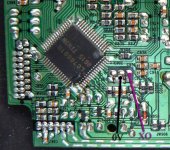
8V is connected right after choke L901 (the choke is recommended to be removed).
There is also 5V supply, based on Q902. If you want to use one super regulator you should probably start with 5V supply; in that case remove transistor Q902 and connect 5V wire from regulator to collector pad, the ground from regulator connects to negative pin of C916. You can also cut the trace from collector output (Q902) and connect external 5V there (that's why you see black wire jumper in some of my pics).
You may also consider 8V super regulator and this would connect right after choke (L901)
Thanks. Final check: if I leave existing 8V regulator, and add a new super 5V, all to do is to remove Q902 and supply it's output pad. As the result crucial circuits are supplied with 5V excelent regulator, and only less critical motors' driver with lower quality 8V, and the noises from motors' supply do not influence 5V supply, right?
Trying to complete Andy´s question:
Are this regs a good choice
http://www.audioupgrades.co.uk/regs.shtml
Thanks
Are this regs a good choice
http://www.audioupgrades.co.uk/regs.shtml
Thanks
brgds said:Thanks. Final check: if I leave existing 8V regulator, and add a new super 5V, all to do is to remove Q902 and supply it's output pad. As the result crucial circuits are supplied with 5V excelent regulator, and only less critical motors' driver with lower quality 8V, and the noises from motors' supply do not influence 5V supply, right?
Yes, but what is excellent and what lower quality is still to be determined
")
I did not remove Q902, only cut traces, but don't see a reason why removal shouldn't work.
JC Fardo said:Trying to complete Andy´s question:
Are this regs a good choice
No, low quality opamp is used as error amplifier so performance is no better.
aparatusonitus said:
No, low quality opamp is used as error amplifier so performance is no better.
I have built a flea supply for the 16.93 crystal that I obtained from Peter Daniel. I have tried to connect it up as in the schematic attached. However the transport is reading the disc and making music even if the flea is turned off. I am also getting a loud buzzing noise.
I assume that I have either got the orientation of the crystal wrong, or that I have to cut the power supply to the point where the crystal was originally attached?
I have attached the crystal as to one leg to the +5v and the other leg to one point on the board. The ground wire from the flea is attached to the other point for the original connection.
http://www.acoustica.org.uk/t/naim/35clockreg.html
Puffin
Are you using the crystal in an external clock circuit - such as this one: http://home.quicknet.nl/qn/prive/ra.vdsteen/pdfs/CD_clock.pdf ? If so, then it will work as Audio1st has just shown. But it won't work with an external supply if you have just got the crystal connected directly to the board.
Are you using the crystal in an external clock circuit - such as this one: http://home.quicknet.nl/qn/prive/ra.vdsteen/pdfs/CD_clock.pdf ? If so, then it will work as Audio1st has just shown. But it won't work with an external supply if you have just got the crystal connected directly to the board.
jonners& Audio1st. Thanks for your replies. I am finding my way here so forgive me if I may not understand. The flea is a regulator to which I have attached the crystal oscillator. The flea is shown in the document I attached previously with a Tent Clock (16.93) attached. It can be used for other applications. I don't know if what I have made would be classed as an external clock circuit or just an external power supply with crystal attached.
I'll post some pics later if it will help.
I'll post some pics later if it will help.
An externally hosted image should be here but it was not working when we last tested it.
Hope this helps
An externally hosted image should be here but it was not working when we last tested it.
jonners said:Puffin
Are you using the crystal in an external clock circuit - such as this one: http://home.quicknet.nl/qn/prive/ra.vdsteen/pdfs/CD_clock.pdf ? If so, then it will work as Audio1st has just shown. But it won't work with an external supply if you have just got the crystal connected directly to the board.
You have me puzzled here. I'm building a separate clock (KC7) with it's own independent PS.
- Home
- Source & Line
- Digital Source
- Finally, an affordable CD Transport: the Shigaclone story