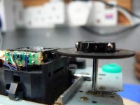
Aw bug*ger! Good on you for trying though. I guess you could alway file away some of the outside circumference until it's clear of the laser sled?
I'd like to post some pictures of how my JVC is progressing, but have lost the lead that connects the camera to the PC - aghhhhh! I'll have to wait for a bit.
- J
I'd like to post some pictures of how my JVC is progressing, but have lost the lead that connects the camera to the PC - aghhhhh! I'll have to wait for a bit.
- J
johnm said:Peter, is it OK to temporarily use the JVC supplied 12v transformer with your PSU board? I cannot afford the new torroidal transformer just yet
Do I need to make any changes to the PSU board, or will the JVC transformer work without any problems?
Many thanks.
- John
Peter Daniel said:JVC transformer should work properly.
I didn't try the original PS at all so can't comment how good it is.
And I'd rather use EI transformer with digital, not toroid.
I can't see it causing any problems short term. I was using the one that came with my boom box both with the stock supply and the one that replaced it, and it seemed adequate. I could be wrong but I suspect the biggest bang for the buck comes from a much improved psu and less from the transformer.
Incidentally in terms of toroid vs. EI type you can achieve similar or superior levels of line noise rejection if you use a good common mode choke ahead of the toroid.. Overall of course a small EI will be less expensive than the choke+toroid combo.
I'm going to look at my existing controller board and see whether or not it is irreparably damaged tonight. I plan to make some changes to the power supply in order to reduce the possibility of damage due to high line. (Basically regulate the 12V to the LCD, and reduced the voltage to the LED back to the original 6V by using another cheap regulator running off of the switched 12V. (This to provide protection in the event of wiring errors, etc., at the display board.) I have another RCEZ32 on the way and believe me I will be extremely careful with both the display and controller. Even minor mechanical shock apparently can damage the display.
johnm said:Aw bug*ger! Good on you for trying though. I guess you could alway file away some of the outside circumference until it's clear of the laser sled?
I'd like to post some pictures of how my JVC is progressing, but have lost the lead that connects the camera to the PC - aghhhhh! I'll have to wait for a bit.
- J
The surface of the disk is likely too close to the optical assembly - a malfunction (power failure for example) could cause the optics to hit the disk even if it worked.
Folks, I have the choice between an Elna Silmic ARS 100uF/63V for C939 (original JVC value is 100uF), or a Black Gate N 47uF / 50V.
Due to the fact that the traces seem to lift easily on the board I only want to install once - no room for experimenting (plus I want to get it soldered up today") ).
).
What would you choose, and does it matter that much in this position?
Many thanks.
- John
P.S. Thanks Kevin I'll use the JVC unit for now then, and upgrade to a better unit at a later stage. Saves something for later tweak-wise
Due to the fact that the traces seem to lift easily on the board I only want to install once - no room for experimenting (plus I want to get it soldered up today
).What would you choose, and does it matter that much in this position?
Many thanks.
- John
P.S. Thanks Kevin I'll use the JVC unit for now then, and upgrade to a better unit at a later stage. Saves something for later tweak-wise
johnm said:Folks, I have the choice between an Elna Silmic ARS 100uF/63V for C939 (original JVC value is 100uF), or a Black Gate N 47uF / 50V.
Due to the fact that the traces seem to lift easily on the board I only want to install once - no room for experimenting (plus I want to get it soldered up today
What would you choose, and does it matter that much in this position?
Many thanks.
- John
P.S. Thanks Kevin I'll use the JVC unit for now then, and upgrade to a better unit at a later stage. Saves something for later tweak-wise
I'm just wondering what sort of soldering iron you are using? I imagine that the RCEZ32 pcb are similar to those in yours and I have not had any problems with lifting traces even when removing smd parts with a conventional iron. Use "soder wick" to remove the solder from the pad (through hole parts) and then remove the part. Make sure you tip is sized appropriately for the work.. I use a 40W temperature controlled Weller running at 700 degrees F.. (~370 C)
I'm using an Antex 25W iron with a 'pencil' tip, and using solder wick.
The other iron I use for large jobs is a Weller 60W job.
I think my close-run incident with the lifted solder pad was just because I was having difficulty unsoldering those SMT capacitors. I've been a bit wary of unsoldering items on the board since...
At some point I will need to get a temperature controlled iron I think... along with a new PSU transformer, a custom built aluminium case for the Shigaclone, a new pair of speakers etc etc etc
- John
Badge said:I am late to the party as usual. Are any of the current offered JVC's using the same components?
No... Your choice is limited to the RCEZ31 or if you are up for a major challenge the RCEZ32 which is still obtainable in the US.
Vladco said:Kevin where are you able to find RCEZ32?
I'm not able to find anything.
Vlad
I may have cornered the supply, but they have been available on eBay up until now. So far I have bought 3.. (One was stolen, one had an experimental accident late the other night, and now the controller may be permanently dead, and another one is on its way.)
When working the RCEZ32 based solution can sound very good. I was pretty impressed after the last round of mods. I will share more details once I know that the thing is actually working again and my mods aren't the cause of the controller problems I am having. (I don't think they are - I can think of two unrelated things I did that might account for the issues.)
johnm said:Wee question: are those Citizen crystals directional? Peter I noticed you'd taken the metal covering off of yours... any benefits?
Hi John,
They aren't directional, and it looks to me like Peter slipped some heat shrink tubing over the metal cylinder that houses the crystal. Removing the housing will probably destroy the crystal. I installed mine without the tubing. (Didn't have any of a small enough diameter, and I am not all that crazy about thermally "distressing"
the crystal with my heat gun anyway.)I read somewhere that it's good to keep the crystal as free from vibrations as possible so it certainly wouldn't have hurt - I'm going to glue gun mine to the circuit board.
Peter - probably a simple question... for an expert - but where do I put links on your PSU board for the 12v dc to get to the main board? I've followed Otapi's DIY PDF to the letter, but I think he left out the bit about needing to jumper from the small board to the big.
- John
Peter - probably a simple question... for an expert
- but where do I put links on your PSU board for the 12v dc to get to the main board? I've followed Otapi's DIY PDF to the letter, but I think he left out the bit about needing to jumper from the small board to the big.- John
- Home
- Source & Line
- Digital Source
- Finally, an affordable CD Transport: the Shigaclone story